Audio reproducing apparatus

a technology for reproducing apparatus and sound, applied in the direction of stereophonic arrangments, transducer details, earpiece/earphone attachments, etc., can solve the problems of limiting speaker layout, unable to independently separate signals, and obtaining sound fields that are extremely strange, so as to suppress the circuit scale, suppress the amount of calculation, and the effect of clear sound-image locating

Inactive Publication Date: 2006-05-09
SONY CORP
View PDF5 Cites 6 Cited by
  • Summary
  • Abstract
  • Description
  • Claims
  • Application Information

AI Technical Summary

Benefits of technology

[0030]The present invention has been made in consideration of the foregoing points. It is an object of the present invention to suppress the circuit scale and the amount of calculation of a signal processing section for locating the reproduced sound image of an input audio signal at any position outside the head of the listener or around the listener to allow the reproduced sound image to be clearly located even if the circuit scale and the amount of calculation are suppressed.
[0031]The foregoing object is achieved in one aspect of the present invention through the provision of an audio reproducing apparatus including first filtering means for convoluting into an input audio signal, an impulse response to which a transfer function from a position where the sound image of the input audio signal is located to the left ear of a listener is converted on a time domain; second filtering means for convoluting into the input audio signal, an impulse response to which a transfer function from the position where the sound image of the input audio signal is located to the right ear of the listener is converted on the time domain; third filtering means for extracting a low-frequency component from the input audio signal; first adder means for adding the output signal of the third filtering means to the output signal of the first filtering means to obtain a first output audio signal; and second adder means for adding the output signal of the third filtering means to the output signal of the second filtering means to obtain a second output audio signal.
[0032]In the audio reproducing apparatus having the above-described structure, according to the present invention, since the low-frequency component of the input audio signal, which is the output signal of the third filtering means, is added to each of the output signals of the first and second filtering means, the level difference between the frequency characteristics of the impulse responses produced by the first and second filtering means becomes slight at low frequencies, and a clear feeling of sound-image locating is obtained at the low frequencies.
[0033]The foregoing object is achieved in another aspect of the present invention through the provision of an audio reproducing apparatus including first filtering means for convoluting into an input audio signal, an impulse response to which a transfer function from a position where the sound image of the input audio signal is located to the left ear of a listener is converted on a time domain; first reverberating means for performing a reverberation processing to the output signal of the first filtering means; second filtering means for convoluting into the input audio signal, an impulse response to which a transfer function from the position where the sound image of the input audio signal is located to the right ear of the listener is converted on the time domain; second reverberating means for performing a reverberation processing to the output signal of the second filtering means; third filtering means for extracting a low-frequency component from the input audio signal; first adder means for adding the output signal of the third filtering means to the output signal of the first reverberating means to obtain a first output audio signal; and second adder means for adding the output signal of the third filtering means to the output signal of the second reverberating means to obtain a second output audio signal.
[0034]The foregoing object is achieved in still another aspect of the present invention through the provision of an audio reproducing apparatus including down-sampling means for down-sampling an input digital audio signal to generate a digital audio signal having a sampling frequency lower than the sampling frequency of the input digital audio signal; first filtering means for convoluting into the down-sampled digital audio signal, an impulse response to which a transfer function from a position where the sound image of the digital audio signal is located to the left ear of a listener is converted on a time domain; first over-sampling means for converting the sampling frequency of the output signal of the first filtering means to the sampling frequency of the input digital audio signal; second filtering means for convoluting into the down-sampled digital audio signal, an impulse response to which a transfer function from the position where the sound image of the digital audio signal is located to the right ear of the listener is converted on the time domain; second over-sampling means for converting the sampling frequency of the output signal of the second filtering means to the sampling frequency of the input digital audio signal; third filtering means for extracting at least a low-frequency component from the input digital audio signal; first adder means for adding the output signal of the third filtering means to the output signal of the first over-sampling means to obtain a first output audio signal; and second adder means for adding the output signal of the third filtering means to the output signal of the second over-sampling means to obtain a second output audio signal.
[0035]The foregoing object is achieved in yet another aspect of the present invention through the provision of an audio reproducing apparatus including a band-restriction filter for extracting a frequency component having a predetermined frequency or lower from an input audio signal; first filtering means for convoluting into the output audio signal of the band-restriction filter, an impulse response to which a transfer function from a position where the sound image of the output audio signal is located to the left ear of a listener is converted on a time domain; second filtering means for convoluting into the output audio signal of the band-restriction filter, an impulse response to which a transfer function from the position where the sound image of the output audio signal is located to the right ear of the listener is converted on the time domain; third filtering means for extracting a low-frequency component from the input audio signal; first adder means for adding the output signal of the third filtering means to the output signal of the first filtering means to obtain a first output audio signal; and second adder means for adding the output signal of the third filtering means to the output signal of the second filtering means to obtain a second output audio signal.

Problems solved by technology

When such sound is reproduced by headphones, however, the sound image produced by an input audio signal is located in the head of the listener, the video position does not match the sound-image locating position, the sound image is located at a position extremely strange, and the sound-image locating position of an each-channel audio signal cannot be independently separated.
Even when only multi-channel sound such as music is listened to, if the sound is reproduced by headphones, unlike a case in which the sound is reproduced by speakers, the reproduced sound image is located in the head of the listener, the sound-image locating positions of the multi-channel audio signal are not separated, and a sound field extremely strange is obtained.
When sound is reproduced by speakers, a speaker layout is usually restricted.
A limited number of listeners can place a great number of speakers for reproducing multi-channel sound in their listening rooms.
In this case, however, if the impulse response such as that shown in FIG. 2 is not sufficiently extended in time for an input audio signal for each channel, reproducibility deteriorates especially at low frequencies of several hundred Hz and lower, and a clear feeling of sound-image locating is not obtained at the low frequencies.
Then, however, when the sound-image-locating signal processing section is formed of hardware, the circuit scale becomes huge, and when the sound-image-locating signal processing section is formed of hardware and software (program) like a digital signal processor (DSP), a huge amount of calculation is required.

Method used


Image

  • Audio reproducing apparatus
  • Audio reproducing apparatus
  • Audio reproducing apparatus

Examples


first embodiment

[0061][ FIG. 1 to FIG. 11]

[0062]A case in which a low-frequency component is extracted from an input audio signal and added to an impulse-response-output audio signal will be described according to a first embodiment.

[0063][Monaural Reproduction by Headphones with FIG. 1 to FIG. 9]

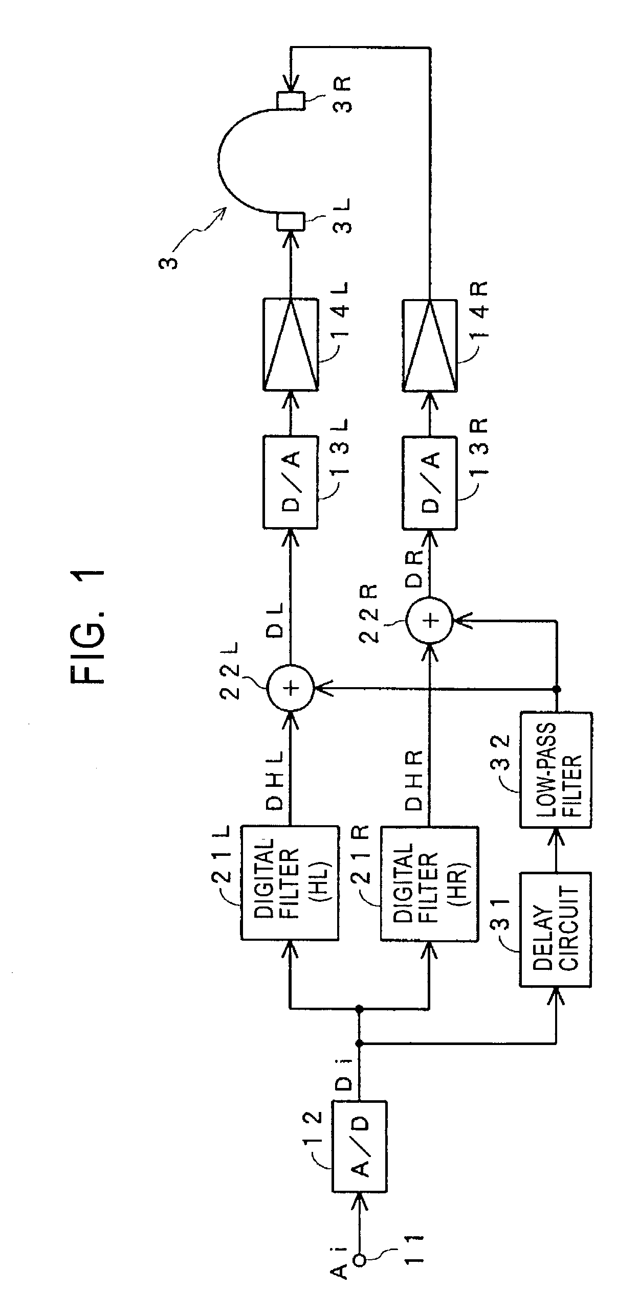
[0064]FIG. 1 shows a case according to the first embodiment, in which one-channel sound is reproduced by headphones with the sound image thereof being located at any position outside the head of the listener, for example, at a position on the center plane before the listener, as shown in FIG. 21.

[0065]In this case, transfer functions HR and HL from a sound source 5 where the sound image is to be located, to the right and left ears 1R and 1L of the listener 1 are measured or calculated in advance.

[0066]In the case shown in FIG. 1, an analog audio signal Ai which corresponds to a signal of the sound source 5 shown in FIG. 21 is input to a terminal 11 and is converted to a digital audio signal Di by an A / D co...

second embodiment

[0099][ FIG. 12 to FIG. 16]

[0100]A case in which a reverberation processing is performed and a low-frequency component of an input audio signal are added to an impulse-response-output audio signal will be described below according to a second embodiment.

[0101][Monaural Reproduction by Headphones: FIG. 12 to FIG. 15]

[0102]FIG. 12 shows a case according to the second embodiment, in which one-channel sound is reproduced by headphones with the sound image thereof being located at any position outside the head of the listener, as shown in FIG. 21.

[0103]In the case shown in FIG. 12, the output signals DHR and DHL of digital filters 21R and 21L are sent to reverberating circuits 23R and 23L, and reverberation processes are performed to the output signals DHR and DHL. An adder circuit 22R adds the output signal of a low-pass filter 32R, which is the same as the low-pass filter 32R shown in FIG. 9, to the output signal of the reverberating circuit 23R, and an adder circuit 22L adds the outpu...

third embodiment

[0118][ FIG. 17 to FIG. 20]

[0119]A case in which down-sampling or bandwidth restriction is applied to an input audio signal, and an impulse response is convoluted will be described according to a third embodiment.

[0120][When Down-Sampling is Applied: FIG. 17 to FIG. 19]

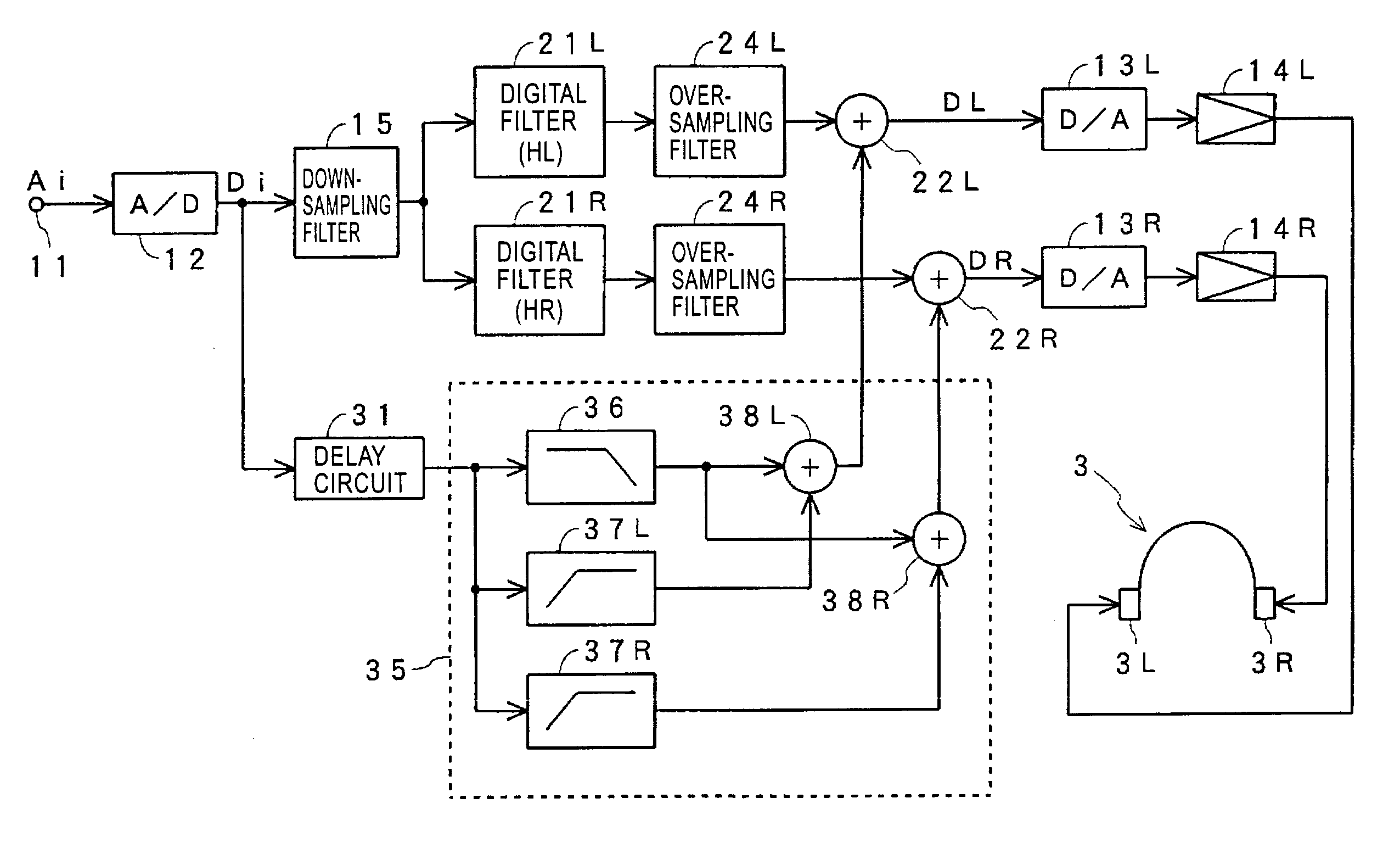
[0121]FIG. 17 shows a case according to the third embodiment, in which, when one-channel sound is reproduced by headphones with the sound image thereof being located at any position outside the head of the listener, as shown in FIG. 21, the input audio signal is down-sampled and an impulse response is convoluted.

[0122]In the case shown in FIG. 17, the output digital audio signal Di of an A / D converter 12 is sent to a down-sampling filter 15, and the sampling frequency of the digital audio signal is reduced to a half of the original frequency, for example, converted from 44.1 kHz to 22.05 kHz. The digital audio signal to which down-sampling has been applied is sent to digital filters 21R and 21L.

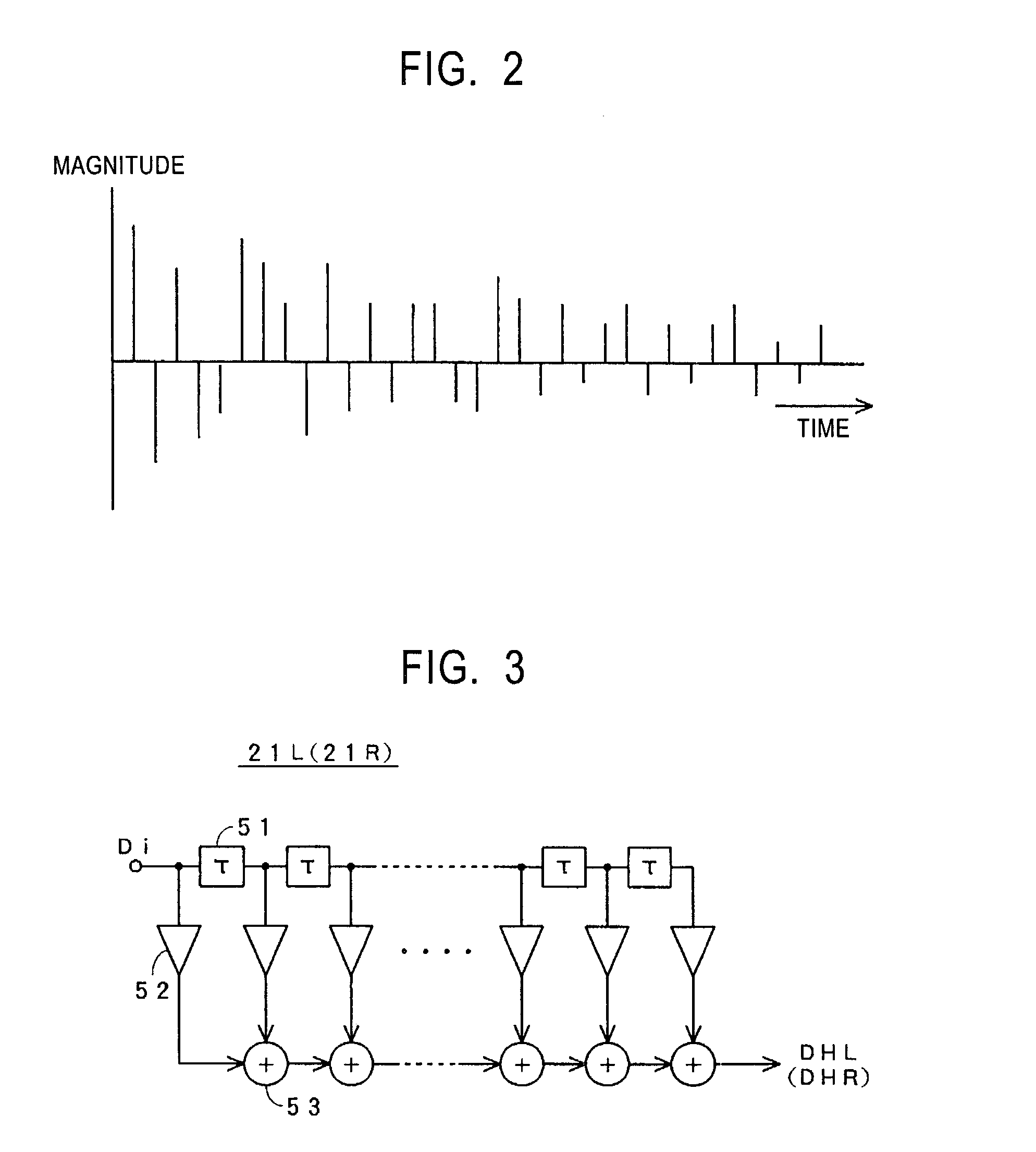
[0123]The digital filte...


PUM


Abstract

In an audio reproducing apparatus, first and second filters convolute impulse responses corresponding to transfer functions from a position where a right-hand sound source is located to the right and left ears of the listener into an audio signal, respectively, and third and fourth filters convolute impulse responses corresponding to transfer functions from a position where a left-hand sound source is located to the right and left ears of the listener into another audio signal, respectively. Fifth and sixth filters extract low-frequency components of the audio signal, and seventh and eighth filters extract low-frequency components of the another audio signal. The output signals of the first, third, fifth, and seventh filters are added, and the output signals of the second, fourth, the sixth, and eighth filters are added.

Description

BACKGROUND OF THE INVENTION[0001]1. Field of the Invention[0002]The present invention relates to apparatuses for reproducing sound by headphones or speakers with the sound image(s) being located at any position(s) outside the head of a listener or around the listener.[0003]2. Description of the Related Art[0004]In recent years, multi-channel audio signals have been used frequently for sound which accompanies video such as movies, and are recorded on the assumption that the sound is reproduced by speakers disposed at both sides and the center of a screen or a display where the video is displayed, and by speakers disposed after or both sides of the listeners. With this, the sound source in the video matches the sound image from which the sound apparently comes, and a sound field having a normal range is obtained.[0005]When such sound is reproduced by headphones, however, the sound image produced by an input audio signal is located in the head of the listener, the video position does n...

Claims


Application Information

Patent Timeline
Patent Type & Authority Patents(United States)
IPC IPC(8): H04R5/02H04R1/10H04S1/00
CPCH04S1/005H04S7/00
Inventor YAMADA, YUJIOKIMOTO, KOYURU
Owner SONY CORP
Why Eureka
Try Eureka