
Device for collecting water from air

a technology for collecting devices and air, applied in the direction of defrosting, separation processes, domestic cooling devices, etc., can solve the problems of unacceptably high operating cost, low water production rate or zero, and high power consumption

Inactive Publication Date: 2006-05-16
UNIV OF MARYLAND
View PDF17 Cites 89 Cited by
  • Summary
  • Abstract
  • Description
  • Claims
  • Application Information

AI Technical Summary

Benefits of technology

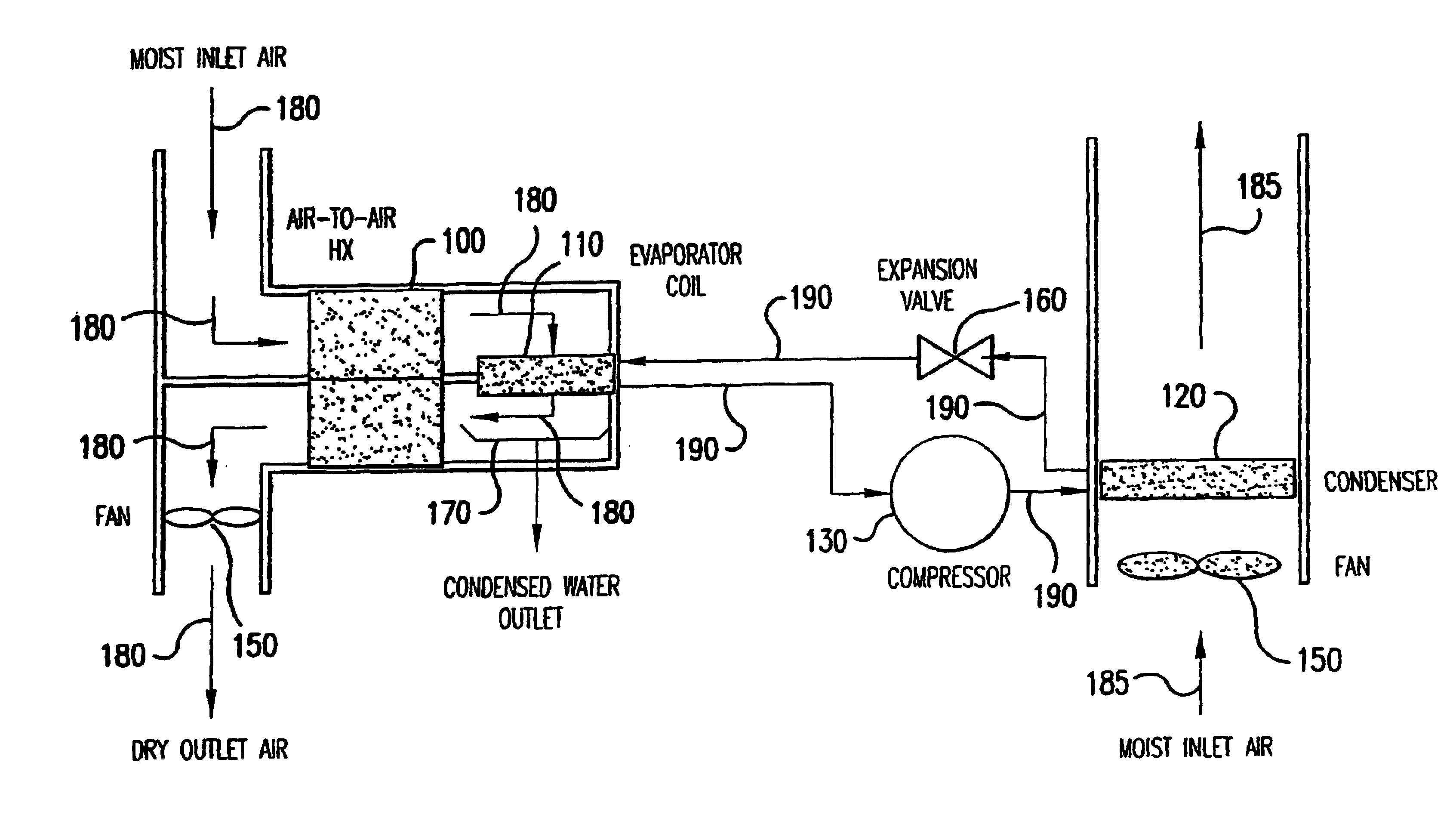
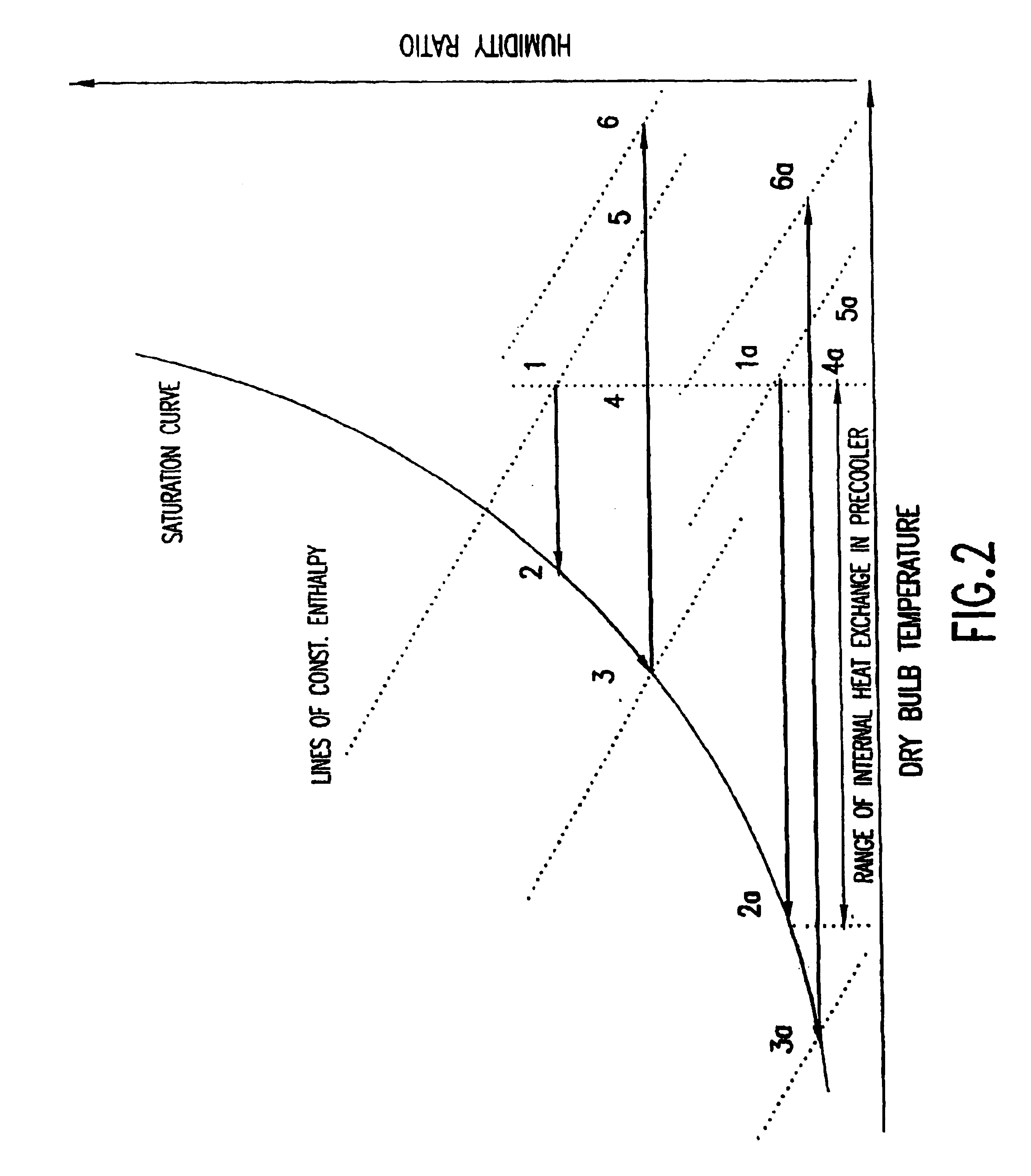
[0010]The present invention solves the need in the art by providing a more reliable water making device, wherein the water production capability is not so sensitive to weather and environmental conditions. In particular, the present invention is directed to a device for collecting water from air particularly well suited for dry, low air temperature environments.

Problems solved by technology

Under low temperature conditions, the water production rate is very low or zero and the power consumption is very high.
The effectiveness of the system, expressed in liters of water per kWh of electricity consumed is very low or zero and accordingly the operating cost unacceptably high.
The inefficiency of the conventional systems results from the fact that for each pound of water produced, a large amount of air has to be cooled below the dew point.
This leads to very large evaporator capacities that do not contribute to the production of water per se.
However, once a user has a water-maker in operation, he will expect water production even under colder and dryer conditions.

Method used


Image

  • Device for collecting water from air
  • Device for collecting water from air
  • Device for collecting water from air

Examples


case 1

[0044] Water maker operation is required, but no water cooling is required. The water level control device (not shown) detects that water needs to be made and turns on compressor 430 and fan 450 for air movement across first evaporator 410. Since second evaporator 415 is assumed to have no cooling load and because expansion valve 460 maintains a certain superheat, superheated refrigerant leaves first evaporator 410 and second evaporator 415 serves just as a section of pipe with no heat transfer duty.

case 2

[0045] Water cooling is required, but no water making operation is required. The thermostat (not shown) of water storage tank 510 calls for cooling and turns on compressor 430 only. Again expansion valve 460 causes a constant superheat at the outlet of second evaporator 415, but all the evaporation of refrigerant occurs within second evaporator 415. First evaporator 410 serves just as a section of tube without any or only very minimal heat transfer. Since in this case, fan 450 for first evaporator 410 is turned off, no air is cooled or moisture condensed.

case 3

[0046] Both water making and water cooling operations are required at the same time. The water level control device detects that water needs to be made and the thermostat of water storage tank 510 (FIG. 5) calls for cooling, such that compressor 430 and fan 450 are turned on. Once again expansion valve 460 controls the superheat at the outlet of second evaporator 415. Now evaporators 410 and 415 both transfer heat, and water is made and cooled simultaneously.

[0047]The thermostatic expansion valve 460 meters the refrigerant flow such that there is always sufficient liquid refrigerant to fulfill the load requirements, while protecting compressor 430 from liquid flooding. A charge control device (not shown) is preferably employed at the outlet of condenser 420, as a receiver, or at the outlet of second evaporator 415, as a suction accumulator. For better control or to obtain higher capacities, two entirely separate refrigeration systems may be employed, one for water making and one for...


PUM

PropertyMeasurementUnit
Flow rateaaaaaaaaaa
Purityaaaaaaaaaa

Abstract

The present invention is directed to a water making device that collects the moisture contained in the atmosphere and condenses it into high purity water. In one embodiment, moist air entering the water making / water cooling system flows across an air filter, then a precooler heat exchanger (where the air stream is cooled to or close to its dew point) and then a water extraction heat exchanger, where the air stream is cooled further and water is extracted. The water that leaves water extraction heat exchanger is collected in a water collection device and passes from there through a primary water filter into a water storage tank. The air stream then passes across a reheat heat exchanger and exhausted to the outside. A water circulation pump extracts water from the water storage tank and circulates the water stream through an evaporator of a vapor compression refrigeration system, where the water stream is chilled, then through the water extraction heat exchanger and precooler, where the incoming air stream is chilled by removing heat to the water stream. The water stream is then circulated through the reheat heat exchanger, where the water stream is again cooled by removing heat to the cool dry air exiting the water extraction heat exchanger. Finally, the cooled water stream is circulated through the water filter to a three way valve, that directs water flow either to a dispenser or back to the water storage tank.

Description

CROSS-REFERENCE TO RELATED APPLICATIONS[0001]This application is a continuation-in-part of U.S. application Ser. No. 10 / 275,061, filed Nov. 1, 2002, which is a U.S. National Phase Application under 35 U.S.C. § 371 of International Application PCT / US00 / 11716, filed May 1, 2000. This application also claims the benefit of U.S. Provisional Application No. 60 / 445,159, filed Feb. 5, 2003, both of which are incorporated herein by reference.BACKGROUND OF THE INVENTION[0002]1. Field of the Invention[0003]The present invention is directed to a device for collecting water from air and more particularly, to a device for collecting the moisture contained in the atmosphere and condensing it into water of high purity.[0004]2. Related Art[0005]Several devices have been previously described for making water from moisture in the atmosphere. For the sake of simplicity, these devices are termed herein “water-makers.” Typically, these systems are based on a refrigeration device operating according to t...

Claims


Application Information

Patent Timeline
IPC IPC(8): F25D21/14B01D5/00E03B3/28
CPCE03B3/28B01D5/0039Y02A20/00
Inventor RADERMACHER, REINHARD K.FAWZI, HISHAM
Owner UNIV OF MARYLAND
Learn More