Gyrostabilized self propelled aircraft

a self-propelled aircraft and gyrostabilized technology, applied in the field of aircraft, can solve the problems of limited versatility of known prior art, inability to use land-based runways, and inability to control the flight speed of aircraft, so as to achieve stable operation and more rapid horizontal flight

a self-propelled aircraft and gyrostabilized technology, applied in the field of aircraft, can solve the problems of limited versatility of known prior art, inability to use land-based runways, and inability to control the flight speed of aircraft, so as to achieve stable operation and more rapid horizontal flight

US7044422B2Inactive Publication Date: 2006-05-16BOSTAN NICOLAE

Image

  • Gyrostabilized self propelled aircraft
  • Gyrostabilized self propelled aircraft
  • Gyrostabilized self propelled aircraft

Examples


Embodiment Construction

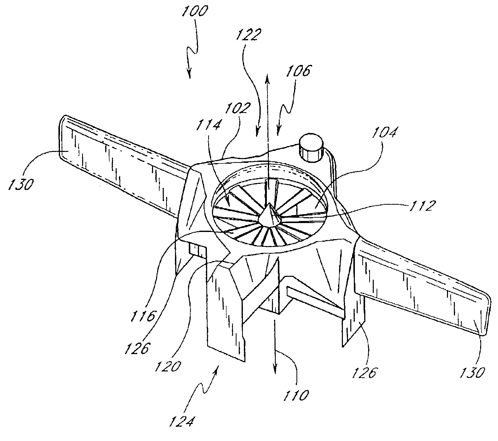
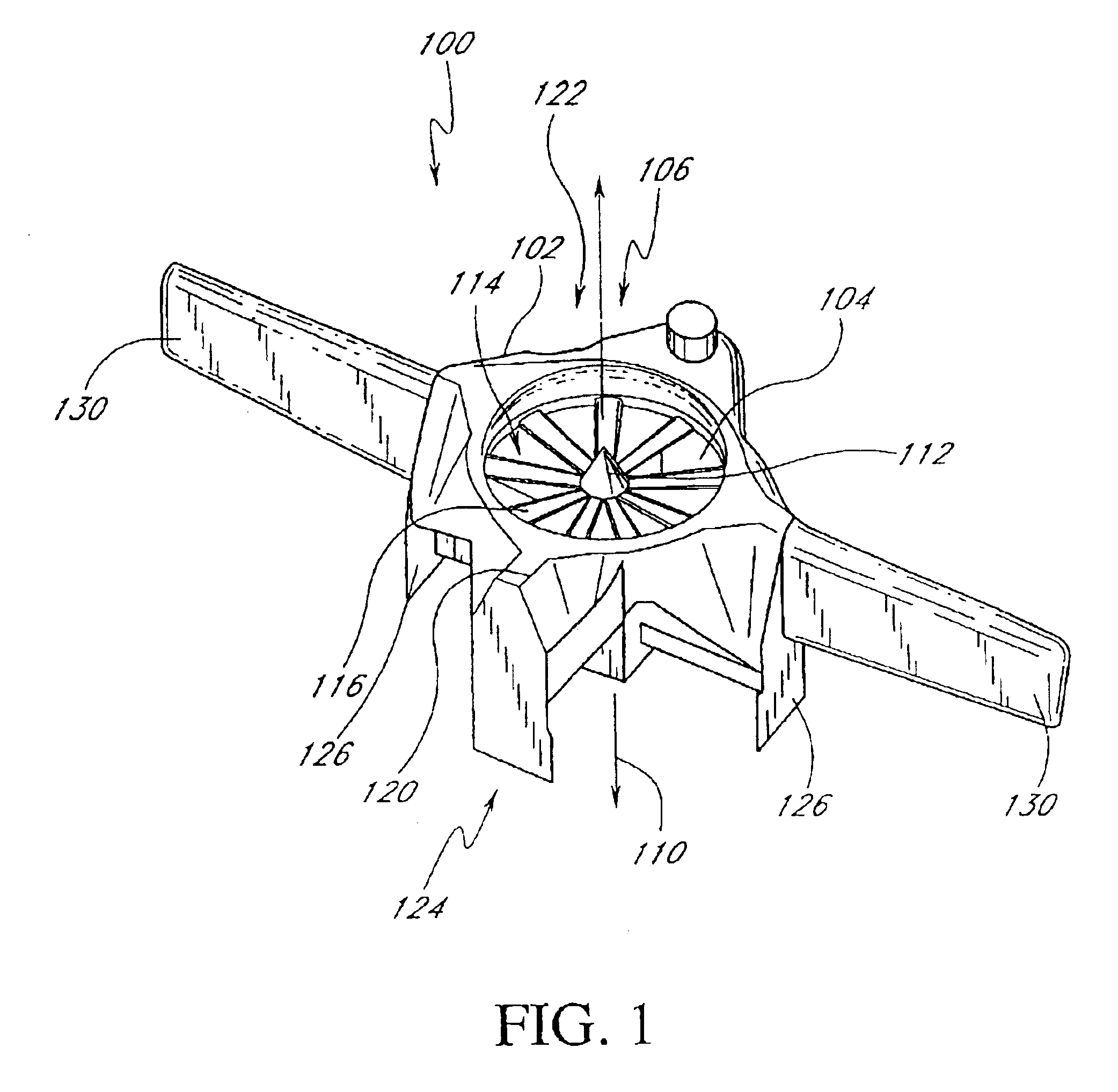
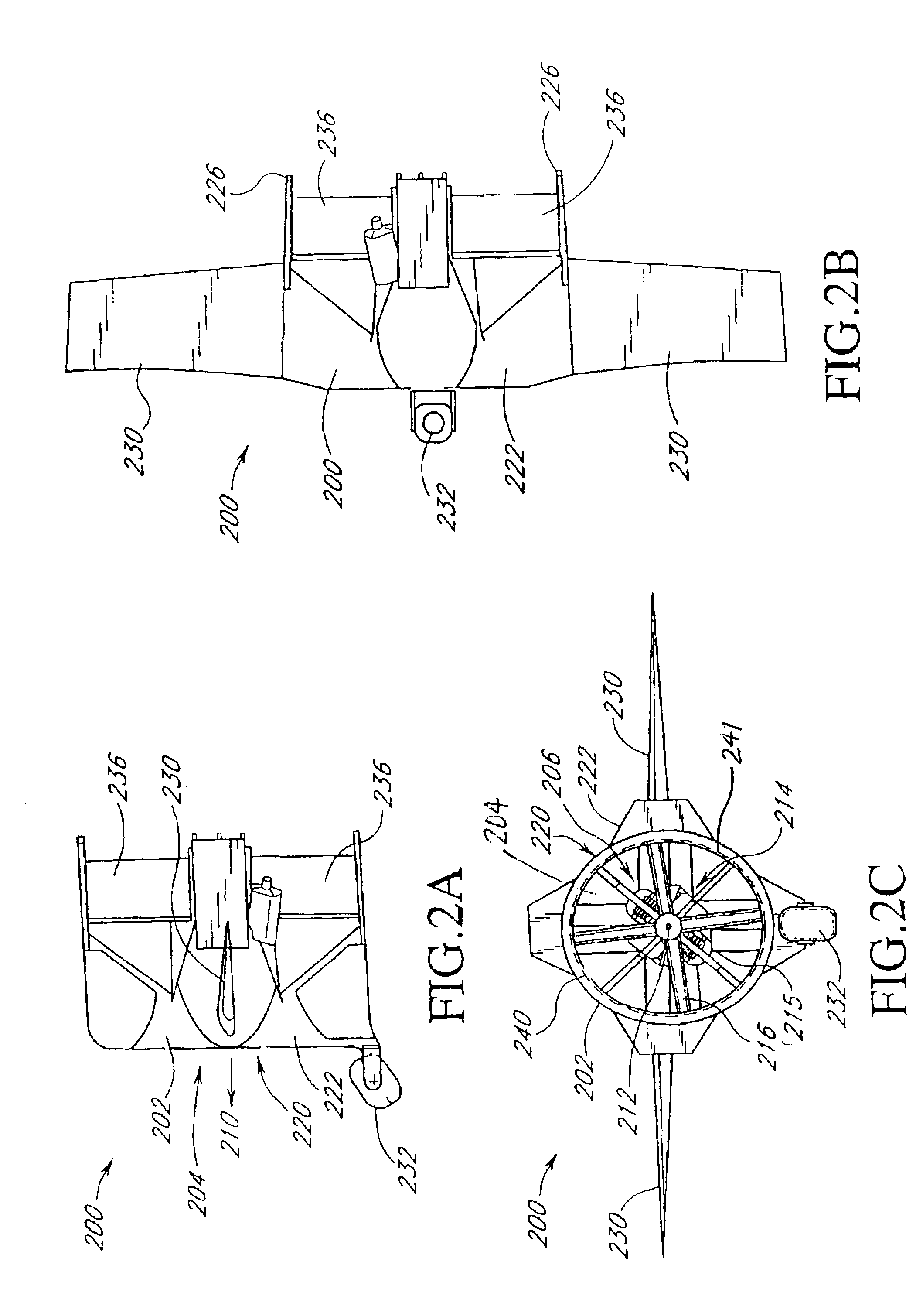
[0027]Reference will now be made to the drawings wherein like numerals refer to like parts throughout. FIG. 1 illustrates an unmanned air vehicle (UAV) 100 that is adapted to be gyroscopically stabilized in a manner that will be described in greater detail below. The UAV 100 in this embodiment has a ducted fan configuration such that a fuselage 102 defines an opening 104 in which a propulsion mechanism 106 is mounted. In this embodiment, the fuselage 102 is generally circular and is generally symmetrical about an axis 110 that extends longitudinally through the opening 104 so as to be coincident with a prop shaft 112 about which a propeller 114 is mounted. As the propeller 114 of the propulsion mechanism 106 is mounted within the opening 104 of the fuselage 102, a configuration of the UAV 100 is generally referred to as a ducted fan configuration as the propeller 114 is mounted within a duct defined by the opening 104. In this embodiment, the propeller 114 incorporates a plurality o...


PUM


Abstract

An unmanned air vehicle comprises a fuselage that defines aerodynamic flight surfaces, an engine mounted to the fuselage having an engine shaft arranged to rotate about a longitudinal axis with respect to the fuselage, and a propeller mounted to the engine shaft so as to rotate to thereby provide thrust. The aircraft also comprises a gyroscopic stabilization member coupled to the shaft such that rotation of the engine shaft results in rotation of the gyroscopic member. Thus, there is more stability during the entire flight envelope. In one embodiment, the gyroscopic stabilization member is comprised of a ring that is attached to the outer ends of the blades of the propeller and the ring is also selected so as to have a mass that will result in the gyroscopic stabilization member having a sufficient angular momentum so as to gyroscopically stabilize the aircraft.

Description

CROSS-REFERENCE TO RELATED APPLICATION(S)[0001]This application is a continuation of U.S. Pat. Appl. 09 / 763,714, filed Feb. 22, 2001 now U.S. Pat. No. 6,604,706, which claims the priority of U.S. Provisional Application 60 / 098,204, filed Aug. 27, 1998.BACKGROUND OF THE INVENTION[0002]The present invention relates to an aircraft and, in particular, concerns an unmanned vertical take-off or landing air vehicle that is gyroscopically stabilized during flights so as to enhance controllability of the flight operations of the vehicle.DESCRIPTION OF THE RELATED ART[0003]Unmanned air vehicles (UAV) are vehicles that provide tremendous utility in numerous applications. For example, UAV's are commonly used by the military so as to provide mobile aerial observation platforms that allow for observation of ground sites at reduced risk to military personnel. The typical UAV used in military applications, and also in other more civilian-type applications, is comprised of an aircraft that has the g...

Claims


Application Information

Patent Timeline
16 May 2006
Publication
US7044422B2
IPC
B64C29/00; B64C17/06; B64C29/02; B64C39/02
CPC
B64C17/06; B64C29/0025; B64C29/02; B64C39/024; B64C2201/162; B64C2201/104; B64C2201/108; B64C2201/127
Inventors
BOSTAN, NICOLAE