Textured electrolyte for a solid oxide fuel cell

a fuel cell and electrolyte technology, applied in the field of fuel cells, can solve the problems of reducing the efficiency of the fuel cell and the power generation system

Active Publication Date: 2006-05-16
BLOOM ENERGY CORP
View PDF31 Cites 82 Cited by
  • Summary
  • Abstract
  • Description
  • Claims
  • Application Information

AI Technical Summary

Benefits of technology

[0120]The present inventors have realized that if at least a portion of at least one surface of the electrolyte is made non-uniform, then several advantages may be realized. The oxygen diffusion through an electrolyte in a solid oxide fuel cell proceeds between so-called “three phase boundaries. These three phase boundaries are electrolyte grain boundary regions at the boundary of an electrode (i.e., cathode or anode) and electrolyte, as shown in FIG. 12. Diffusing oxygen makes up the third “phase.” If the active portions of one or both major surfaces of the electrolyte are made non-uniform, then the surface area between the electrolyte and the electrode contacting the non-uniform surface is increased. The “active portion” of the electrolyte is the area between the electrodes that generates the electric current. In contrast, the peripheral portion of the electrolyte is used for attaching the electrolyte to the fuel cell stack and may contain fuel and oxygen passages. The increased surface area results in more three phase boundary regions, which allows more oxygen to diffuse through the electrolyte. This increases the power density (i.e., watts per cm2) of the fuel cell and decreases the cost per watt of the fuel cell. Furthermore, the non-uniform surface, such as a textured or roughened electrolyte surface provides better adhesion to the adjacent electrodes of the fuel cell due to improved mechanical interlocking.

Problems solved by technology

However, these methods are generally inefficient because they require the use of power (i.e., electricity), thus decreasing the efficiency of the fuel cell and the power generation system.

Method used


Image

  • Textured electrolyte for a solid oxide fuel cell
  • Textured electrolyte for a solid oxide fuel cell
  • Textured electrolyte for a solid oxide fuel cell

Examples


first embodiment

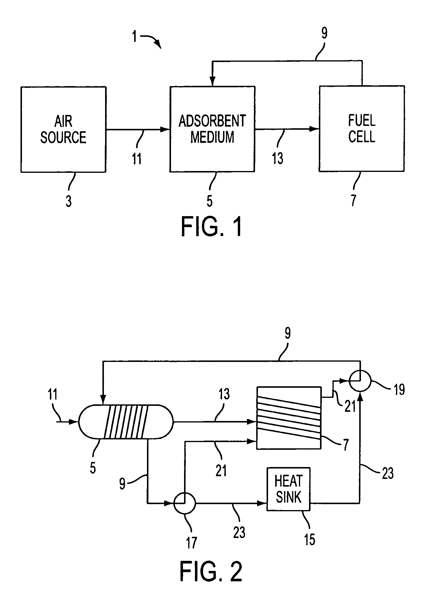
[0021]In one preferred aspect of the first embodiment, the heat transfer conduit 9 comprises a pipe which is located adjacent to the fuel cell 7, adjacent to a heat sink 15 and adjacent to the adsorbent medium 5. For example, as shown in FIG. 2, the conduit 9 is wrapped around the housing of the adsorbent medium 5 and around the fuel cell 7. The conduit 9 also passes through the heat sink 15. The heat transfer conduit 9 transfers a heated heat transfer liquid, such as water, from adjacent to the fuel cell 7 to the adsorbent medium 5. The heated heat transfer liquid heats the adsorbent medium 5 to desorb nitrogen from the adsorbent medium 5. The heat transfer conduit 9 also transfers a cooled heat transfer liquid, such as water, from adjacent to the heat sink 15 to the adsorbent medium 5. The cooled heat transfer liquid cools the adsorbent medium 5, which allows the adsorbent medium 5 to adsorb nitrogen from air that is being provided from inlet 11.

[0022]The operation of the heat tra...

second embodiment

[0095]FIG. 8B illustrates another preferred aspect of this invention. The system illustrated in FIG. 8B shows an alternative preferred routing of the heat streams shown in FIG. 7. The system depicted in FIG. 8B is similar to the system depicted in FIG. 8A, with the exception that the oxidizer cooling heat 60 is provided to the heat exchanger 4 as the high temperature heat 10, and the burner exhaust heat 64 is provided to the oxidizer preheater 24 as oxidizer preheat 62. Thus, the oxidizer outlet conduit 46 is provided into the heat exchanger of the heat pump 4 and then into the burner 30, while the burner exhaust conduit 50 is provided into the burner exhaust heat exchanger 32. Both the heat transfer from the oxidizer cooling heat 60 to the high temperature heat 10 and the burner exhaust heat 64 to the oxidizer preheat 62 can be realized with heat exchangers. Thus, the oxidizer preheater 24 and the burner exhaust heat exchanger 32 are combined as a single component and comprise port...

third embodiment

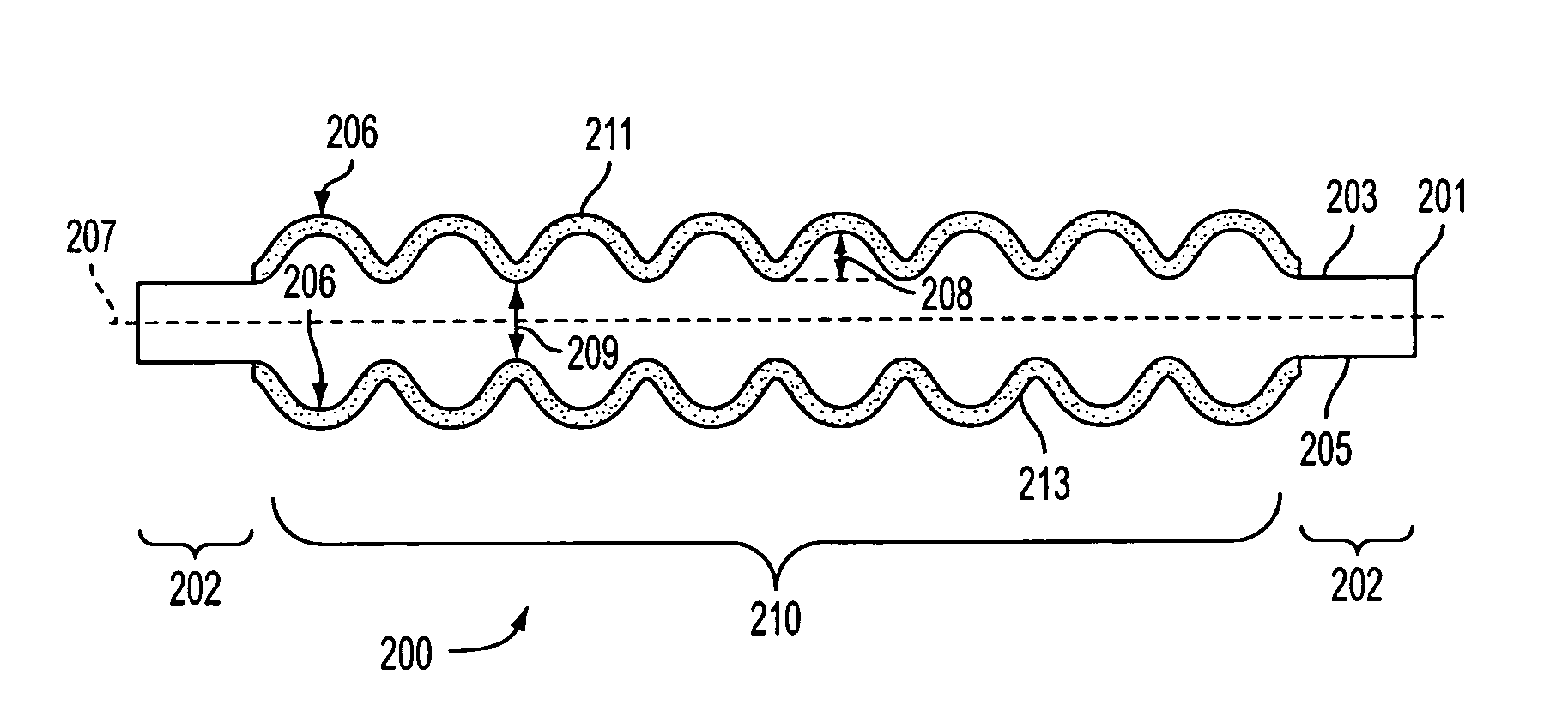
[0121]FIG. 13 illustrates a solid oxide fuel cell 200 containing a ceramic electrolyte 201 having at least one non-uniform surface portion, according to a first preferred aspect of the The at least one non-uniform surface in the first preferred aspect is a textured surface. Preferably, two opposing major surfaces 203, 205 are textured. A textured surface 203, 205 contains a plurality of protrusions (i.e., bumps, peaks, etc.) 206 having a height 208 that is 5% or less, preferably 1% or less of an average electrolyte thickness 209. In a preferred aspect of this embodiment, the electrolyte is textured to obtain an electrolyte having a surface roughness of 0.5 to 2.5 microns, preferably 1 to 2 microns. This surface roughness possesses good adhesion to common SOFC electrodes. The height and width of the protrusions 206 is exaggerated in FIG. 13 for clarity. The protrusions 206 may have any desired shape, such as rectangular, polygonal, triangular, pyramidal, semi-spherical or any irregu...


PUM

PropertyMeasurementUnit
roughnessaaaaaaaaaa
temperaturesaaaaaaaaaa
surface roughnessaaaaaaaaaa

Abstract

A ceramic electrolyte for a solid oxide fuel cell includes at least one non-uniform surface portion. Preferably, the electrolyte surface is textured.

Description

FIELD OF THE INVENTION[0001]This application claims benefit of priority of U.S. provisional application 60 / 357,636 filed on Feb. 20, 2002, which is incorporated by reference in its entirety. The present invention is directed generally to fuel cells and more particularly to ceramic electrolytes for solid oxide fuel cells.BACKGROUND OF THE INVENTION[0002]Fuel cells generate electricity from hydrogen or various hydrocarbon fuels. In some fuel cells, an oxygen containing gas, such as air, is provided onto the cathode side of the electrolyte, while hydrogen or a hydrocarbon fuel is provided onto the anode side of the electrolyte. The fuel cell generates electricity through an electrochemical reaction. For example, in a solid oxide fuel cell, oxygen containing air is provided onto the cathode side of a solid ceramic electrolyte, while a hydrocarbon fuel is provided onto the anode side of the electrolyte.[0003]Fuel cells operate more efficiently when the oxygen content of the inlet air is ...

Claims


Application Information

Patent Timeline
Patent Type & Authority Patents(United States)
IPC IPC(8): H01M8/10H01M4/86C04B35/64C04B38/00H01MH01M2/00H01M2/08H01M4/00H01M4/88H01M4/90H01M8/00H01M8/02H01M8/04H01M8/06H01M8/12
CPCH01M8/04022H01M8/0662H01M8/0247Y02B90/16H01M8/04007H01M8/04111H01M8/04141H01M8/04291H01M2008/1293H01M2250/00H01M2250/40H01M2250/405H01M2300/0074Y02E60/56Y10S429/901Y02E60/50Y02E60/525H01M8/028Y02B90/10H01M8/06H01M8/04H01M8/24
Inventor SRIDHAR, K. R.NGUYEN, DIEN
Owner BLOOM ENERGY CORP
Why Eureka
Try Eureka