

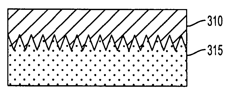
Textured electrolyte for a solid oxide fuel cell
a fuel cell and electrolyte technology, applied in the direction of ceramicware, cell components, cell component details, etc., can solve the problems of reducing the efficiency of the fuel cell and the power generation system
- Summary
- Abstract
- Description
- Claims
- Application Information
AI Technical Summary
Benefits of technology
Problems solved by technology
Method used
Image

Examples
fifth embodiment
In the present invention, the inventor has realized that the solid oxide fuel cell system can be simplified, when feeding a hydrocarbon fuel directly to the solid oxide fuel cell anode for internal reforming to a hydrogen rich reactant by supplying the reforming process steam from the anode exhaust enthalpy recovery. In other words, only the product water (i.e., water vapor) is added to the fuel provided into the anode.
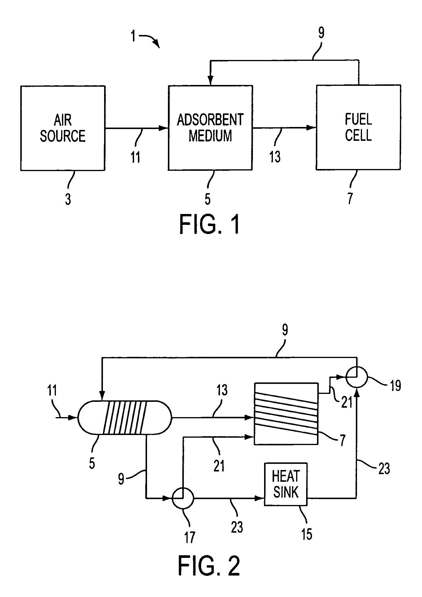
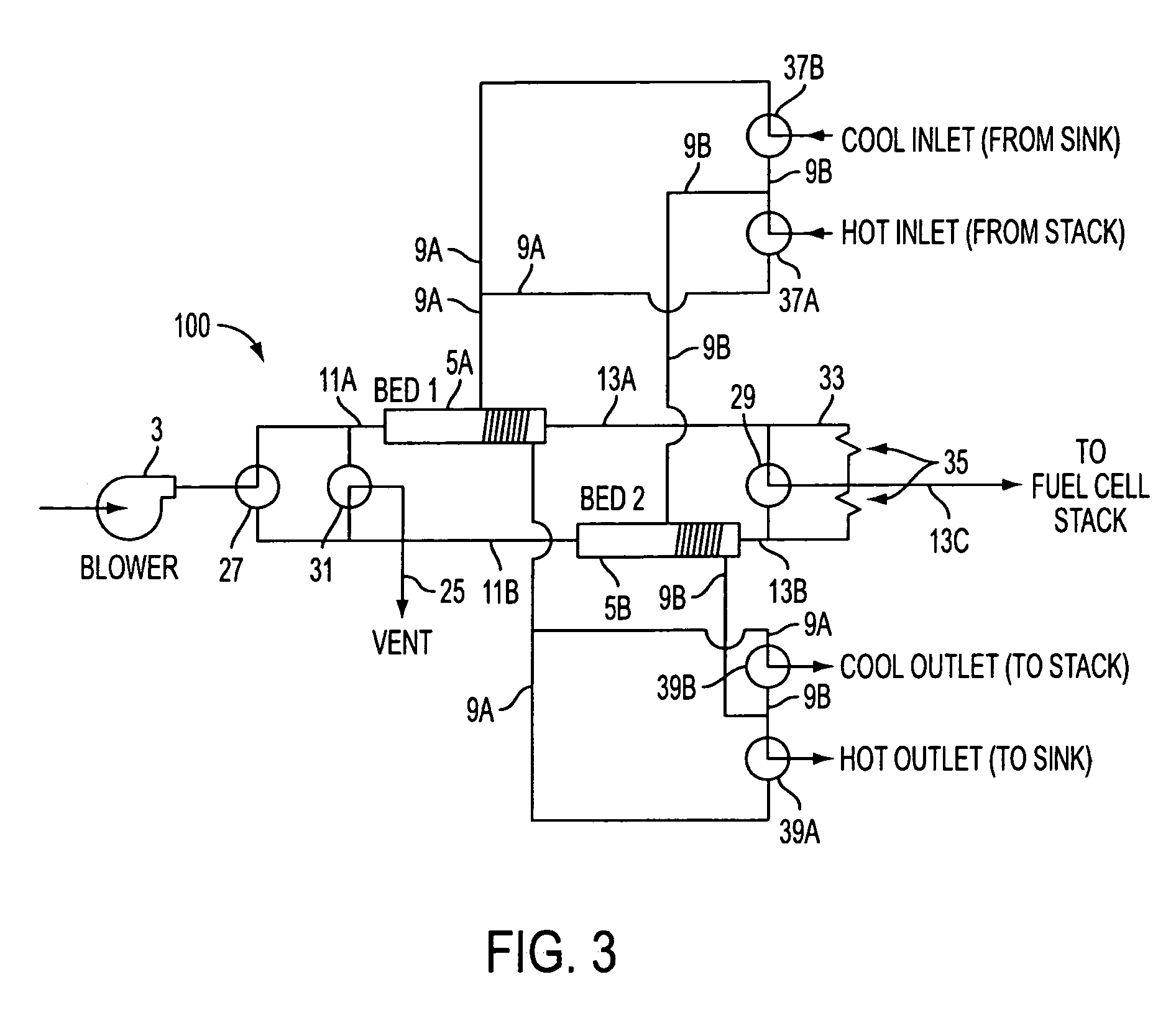
In the low temperature PEM fuel cells, cathode enthalpy is recovered and returned to the cathode inlet to prevent the dry out of the water saturated membrane. In this case, the incoming oxidant air is humidified and membrane dry out is avoided. Several methods have been developed to accomplish this water and heat transfer including hydrated membranes, water injection, and cycling desiccants. One method includes using a device called an enthalpy wheel. The enthalpy wheel is a porous cylindrical wheel with internal passages that are coated with desiccant. It rotates sl...
PUM
| Property | Measurement | Unit |
|---|---|---|
| roughness | aaaaa | aaaaa |
| temperatures | aaaaa | aaaaa |
| height | aaaaa | aaaaa |
Abstract
Description
Claims
Application Information