Circuit arrangement for an electric appliance

a technology for electric appliances and circuits, applied in the direction of electric pulse generators, electric variable regulation, base element modifications, etc., can solve the problems of considerable quiescent current consumption, touch control maintenance ready, operating concept of touchless switches to be disrupted, etc., to achieve easy cleaning and reduce production costs of the operating surface.

Inactive Publication Date: 2006-05-16
SCHOTT AG
View PDF6 Cites 5 Cited by
  • Summary
  • Abstract
  • Description
  • Claims
  • Application Information

AI Technical Summary

Benefits of technology

[0009]It is one object of this invention to provide a circuit arrangement for an electric appliance which simply permits the placement of the electric appliance into service out of a rest state without the consumption of quiescent current and to place it into a rest state without consumption of quiescent current when it is switched off. The circuit arrangement in accordance with this invention is also intended to make it possible to avoid use of mechanical switches, which require an opening in the operating surface, and thus to minimize the production costs of the operating surface and to make it easy to clean.

Problems solved by technology

One disadvantage is that the touch controls must be maintained ready, to be able to react to inputs.
Typically, the power consumption is about 1 W. Although such a power consumption is relatively low, overall it can result in a considerable quiescent current consumption in connection with a large number of conventional devices.
However, it is disadvantageous for the operating concept of touchless switches to be disrupted.
Thus the operating surface must have an opening that increases production costs for such an operating surface, cleaning is more difficult, and it is necessary to accept limitations in the design.
However, the use of a Reed contact is disadvantageous because a magnet is required for activation, which is easily lost under certain circumstances.
However, the consumption in the still remaining stand-by time is disadvantageous, because the energy consumption of the central control device is used during the entire day.

Method used


Image

  • Circuit arrangement for an electric appliance
  • Circuit arrangement for an electric appliance

Examples


Embodiment Construction

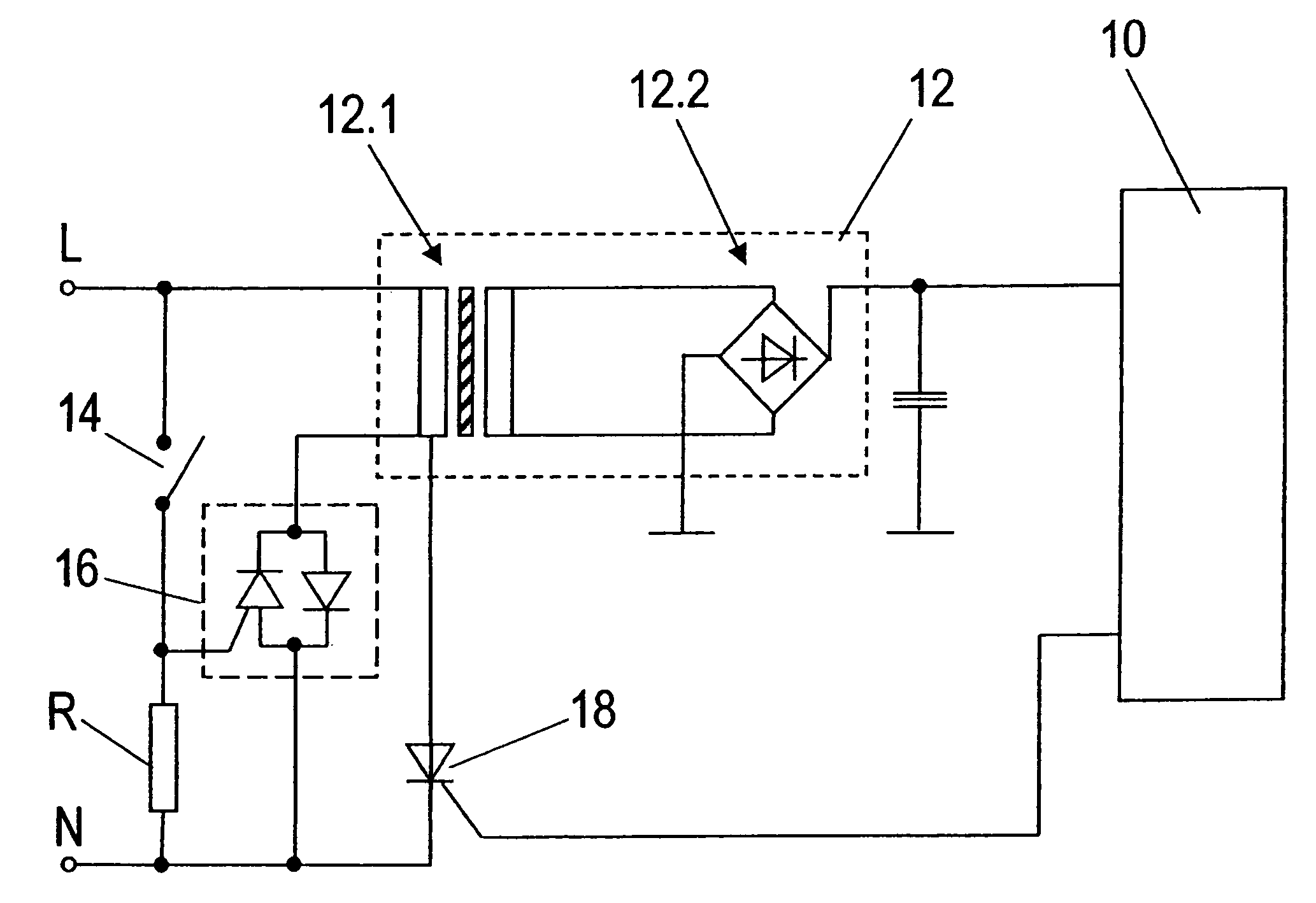
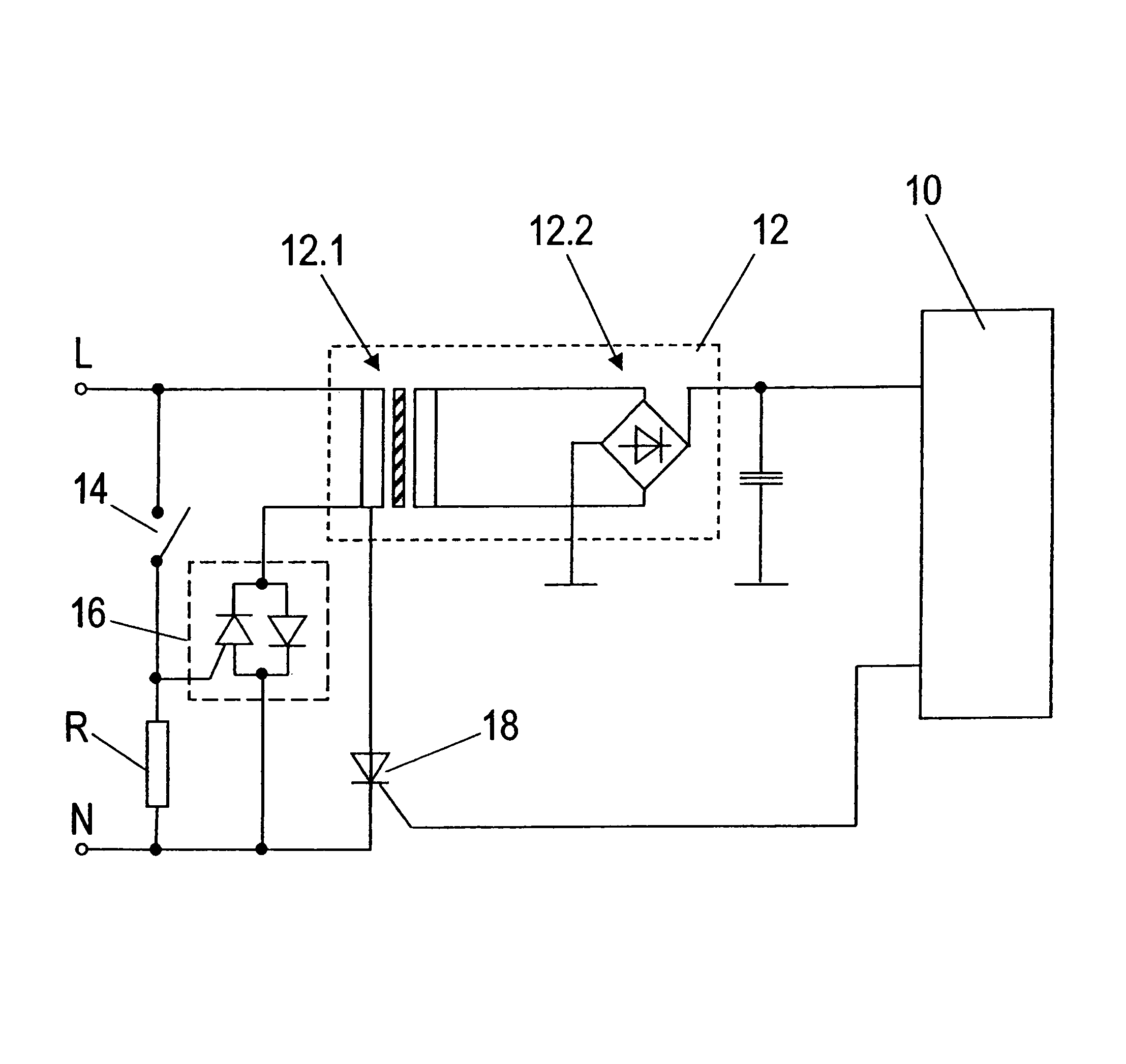
[0020]The circuit arrangement has an electric power supply connector with two individual connectors L and N. A series circuit including a piezo switch 14 and a resistor R is provided on the circuit side between the electric power supply connectors L and N.

[0021]On a primary side the voltage supply connector L is connected with a connector of a transformer 12.1. The second connector on the primary side of the transformer 12.1 is switched together via a triac 16 with the electric power supply connector N and via a thyristor 18 with the electric power supply connector N. A control connection of the triac 16 is switched between the piezo switch 14 and the resistor R. The control connection of the thyristor 18 is connected with a control device 10. The two connections of the transformer 12.1 on the secondary side are switched together with a rectifier bridge 12.2, having an output side connected with the control device 10. Together, the transformer 12.1 and the rectifier bridge 12.2 form...


PUM


Abstract

A circuit arrangement for an electric appliance, having a control device and a power supply unit connected with an electric current supply connector for providing functional units, which are to be controlled, of the electric appliance with current. A switch is provided on the electric current supply connector for cutting off the power supply unit from the electric current supply connector on a primary side. The switch has a piezo switch which is open in the non-activated state. The circuit arrangement of this invention is used, for example, in connection with electronic household appliances.

Description

BACKGROUND OF THE INVENTION[0001]1. Field of the Invention[0002]This invention relates to a circuit arrangement for an electric appliance, having a control device and a power supply unit connected with an electric current supply connector for providing functional units, which are to be controlled, of the electric appliance with current, wherein there is a switch on the electric current supply connector for cutting off the power supply unit from the electric current supply connector on a primary side.[0003]2. Discussion of Related Art[0004]It is known to equip electric appliances used, for example in the household, with electronic controls. Electronic touch controls are employed in particular for stove top cooking units, stoves, dishwashers, washing machines and similar household appliances. One disadvantage is that the touch controls must be maintained ready, to be able to react to inputs. In the process, known appliances use a so-called quiescent current that is determined by the p...

Claims


Application Information

Patent Timeline
Patent Type & Authority Patents(United States)
IPC IPC(8): H02B1/24H02M7/155H01H9/54H03K17/965
CPCH01H9/547H03K17/964H03K17/725H01H2239/076
Inventor ENGELMANN, HARRYSCHAUPERT, KURT
Owner SCHOTT AG
Why Eureka
Try Eureka