Magnetic sensor with variable sensitivity

a variable sensitivity, magnetic sensor technology, applied in the direction of material magnetic variables, stray field compensation, instruments, etc., can solve the problems of saturating and becoming inoperative in larger magnetic fields, difficult to measure small 60 hz currents, and limited dynamic range of most magnetic sensors used to measure electrical current flow

Inactive Publication Date: 2006-05-16
UNITED STATES OF AMERICA THE AS REPRESENTED BY THE SEC OF THE ARMY
View PDF14 Cites 68 Cited by
  • Summary
  • Abstract
  • Description
  • Claims
  • Application Information

AI Technical Summary

Benefits of technology

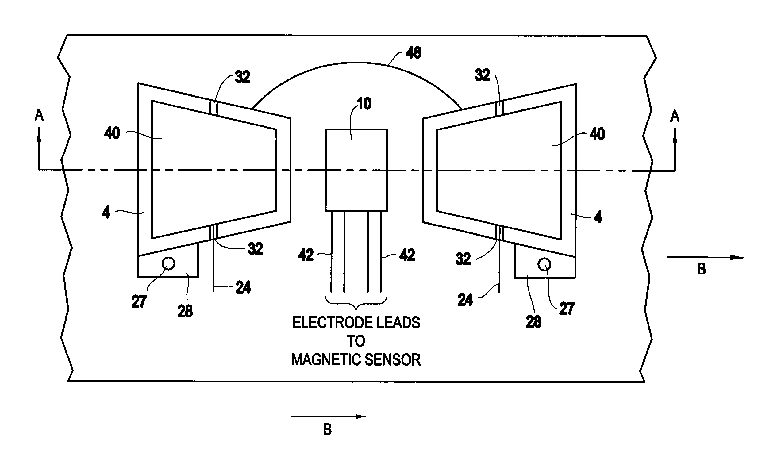
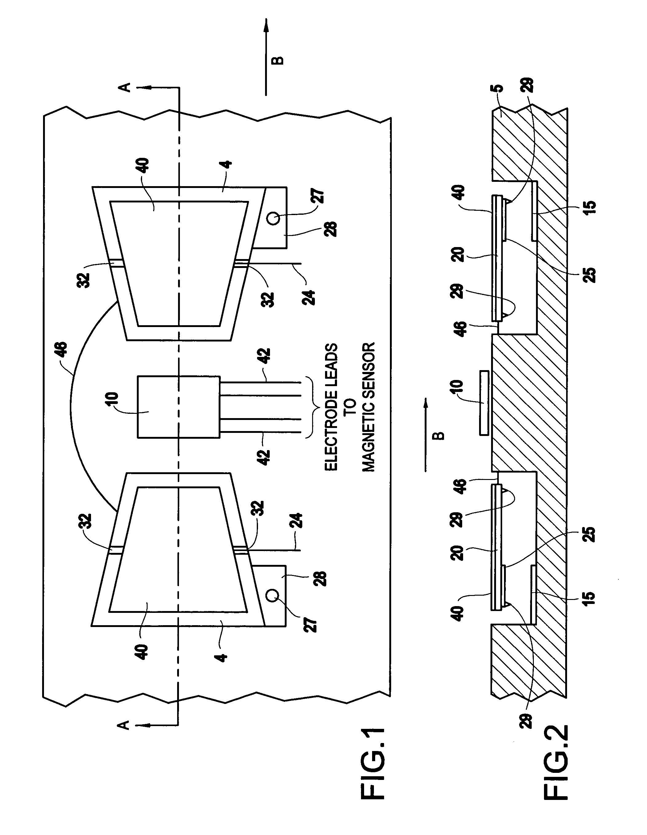
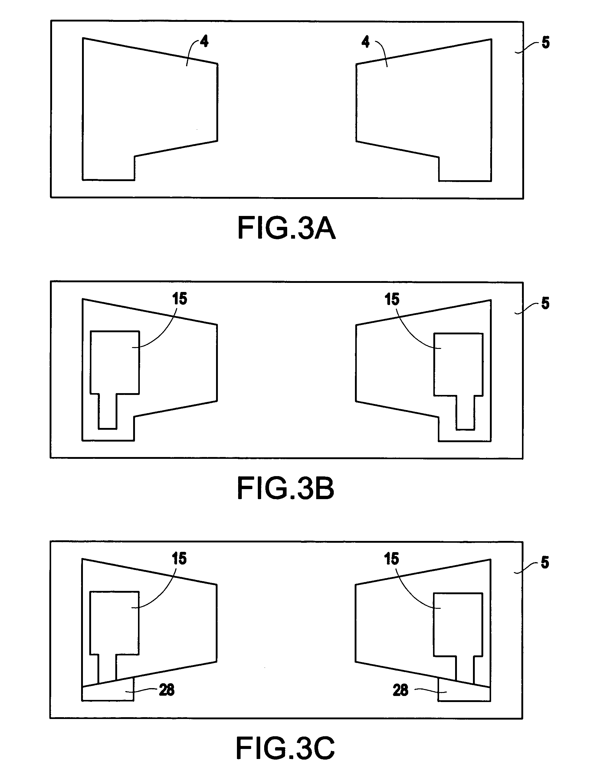
[0020]In another embodiment, the invention provides a low-frequency microelectromechanical modulating magnetic field transducer comprising a base structure; a magnetic sensor attached to the base structure and operable for receiving a DC voltage and an AC modulation voltage in the MEMS device; a flap on either side of the magnetic sensor, each flap including a flux concentrator; a pair of electrostatic comb drives, each coupled to a respective flux concentrator such that a first half of each comb drive is attached to the base structure opposite from a corresponding second half of each comb drive that is attached to the flux concentrator such that when the pair of electrostatic comb drives are excited by a modulating electrical signal, each flux concentrator oscillates linearly at a prescribed frequency thereby minimizing 1 / f-type noise, where f is a frequency of operation of the magnetic sensor; at least one mechanical spring connector connecting the flaps to one another; wherein the DC voltage increases a spacing between the flux concentrators, wherein the flux concentrators are modulated to increase an operating frequency to eliminate 1 / f-type noise, and wherein the AC modulation voltage increases the operating frequency of the magnetic sensor. Another advantage of the invention is that since the signal is modulated, the problem of the DC offset, described above, can be simply eliminated by passing the signal through a high pass filter or amplifier.
[0021]These, and other aspects and advantages of the invention will be better appreciated and understood when considered in conjunction with the following description and the accompanying drawings. It should be understood, however, that the following description, while indicating preferred embodiments of the invention and numerous specific details thereof, is given by way of illustration and not of limitation. Many changes and modifications may be made within the scope of the invention without departing from the spirit thereof, and the invention includes all such modifications.

Problems solved by technology

Conventionally, most magnetic sensors used to measure electrical current flow have a limited dynamic range.
If they are very sensitive, they will saturate and become inoperative in larger magnetic fields.
For example, it is difficult to measure small 60 Hz currents because of the presence of 60 Hz background noise.
Such devices do not lend themselves for applications requiring greater sensitivity, such as required in brain scan devices and magnetic anomaly detection devices.
Flux gate magnetometers use a magnetic core surrounded by an electromagnetic coil, and are difficult to microfabricate.
Additionally, flux gate magnetometers require a relatively large amount of power and accordingly do not lend themselves to a low-cost, compact, portable design.
However, because SQUIDS include a superconducting element, these apparatus must include cooling means at liquid gas temperatures, making them extremely bulky and expensive to operate.
Also, their relatively large size limits their utility because the active superconducting element cannot be placed directly adjacent to the source of the magnetic field.
Furthermore, magnetic sensors used to detect objects that move slowly typically possess considerably low frequency 1 / f-type noise, which is an unwanted condition.
Generally, there is a tendency for such devices, which have higher sensitivity, to also exhibit higher 1 / f-type noise.
This type of noise generally occurs when using magnetoresistive-type magnetic sensors.
Another problem with many magnetic sensors is that the change in signal due to the magnetic field is small compared with the background signal that will be referred to as the DC offset.
However, the limitations of this device, and others like it, include the need for a cryogenic operation, which inherently does not lend to relatively low cost, low power use.

Method used


Image

  • Magnetic sensor with variable sensitivity
  • Magnetic sensor with variable sensitivity
  • Magnetic sensor with variable sensitivity

Examples


Embodiment Construction

[0034]The invention and the various features and advantageous details thereof are explained more fully with reference to the non-limiting embodiments that are illustrated in the accompanying drawings and detailed in the following description. It should be noted that the features illustrated in the drawings are not necessarily drawn to scale. Descriptions of well-known components and processing techniques are omitted so as to not unnecessarily obscure the invention. The examples used herein are intended merely to facilitate an understanding of ways in which the invention may be practiced and to further enable those of skill in the art to practice the invention. Accordingly, the examples should not be construed as limiting the scope of the invention.

[0035]As previously mentioned, there is a need for small, low-cost, low-power-consuming magnetic sensors having enhanced sensitivities capable of meeting the varied applications listed above for detecting low frequency signals and minimizi...


PUM


Abstract

A microelectromechanical system (MEMS) device comprising a base structure; a magnetic sensor attached to the base structure and operable for sensing a magnetic field and allowing for a continuous variation of an amplification of the magnetic field at a position at the magnetic sensor; and for receiving a DC voltage and an AC modulation voltage in the MEMS device; a pair of flux concentrators attached to the magnetic sensor; and a pair of electrostatic comb drives, each coupled to a respective flux concentrator such that when the pair of electrostatic comb drives are excited by a modulating electrical signal, each flux concentrator oscillates linearly at a prescribed frequency; and a pair of bias members (mechanical spring connectors) connecting the flux concentrators to one another.

Description

GOVERNMENT INTEREST[0001]The invention described herein may be manufactured, used, and / or licensed by or for the United States Government.BACKGROUND OF THE INVENTION[0002]1. Field of the Invention[0003]The invention generally relates to magnetic transducers, and more particularly to magnetic sensors used with microelectromechanical system (MEMS)-type components.[0004]2. Description of the Related Art[0005]Conventionally, most magnetic sensors used to measure electrical current flow have a limited dynamic range. If they are very sensitive, they will saturate and become inoperative in larger magnetic fields. As such, there is a need to increase this dynamic range. The measurement of electrical currents may be affected by 1 / f noise and by signals from other sources. For example, it is difficult to measure small 60 Hz currents because of the presence of 60 Hz background noise. Thus, there is a need to mitigate the effect of 1 / f noise and other sources of magnetic fields.[0006]Interest i...

Claims


Application Information

Patent Timeline
Patent Type & Authority Patents(United States)
IPC IPC(8): G01R33/02G01R33/025G01R33/06
CPCG01R33/0286G01R33/02
Inventor EDELSTEIN, ALAN S.
Owner UNITED STATES OF AMERICA THE AS REPRESENTED BY THE SEC OF THE ARMY
Why Eureka
Try Eureka