Digital video synchronizer with both decoded digital and undecoded analog outputs

a digital video and output technology, applied in the field of digital video synchronizers, can solve the problems of insufficient transparency of the process and visible defects in the output signal, and achieve the effect of high quality freez

Inactive Publication Date: 2006-05-16
FORTEL DTV
View PDF28 Cites 17 Cited by
  • Summary
  • Abstract
  • Description
  • Claims
  • Application Information

AI Technical Summary

Benefits of technology

[0007]The purpose of this invention is to meet the need identified above without the cost associated with two independent synchronizers. There are also other benefits that come from combining the two operating modes including high quality freeze for still frames and hot switch, and the ability to switch between the fully transparent and the re-encoded outputs depending on the source of the video being synchronized.
[0011]An important difference between this video synchronizer and prior art systems is that the video synchronizer described herein provides a clean composite video output that has not been decoded and re-encoded while simultaneously providing a decoder to produce a serial digital component output and an encoder to produce a composite signal from a serial digital input. Several new circuits were invented as well as unique ways of sharing circuits to reduce the overall circuitry and cost of the device. Several functions common to composite synchronizers and some digital component synchronizers such as chroma gain, hue control, freezing video, hot switch, vertical interval data and test signal processing and sync and burst regeneration or pass are also processed in a unique way.

Problems solved by technology

Unfortunately, this process is not nearly as transparent as the previous process.
The errors are caused by the problems inherent in the operation of a comb filter and the decoding and encoding process.
These errors cause visible defects in the output signal, particularly after several generations of processing.

Method used


Image

  • Digital video synchronizer with both decoded digital and undecoded analog outputs
  • Digital video synchronizer with both decoded digital and undecoded analog outputs

Examples


Embodiment Construction

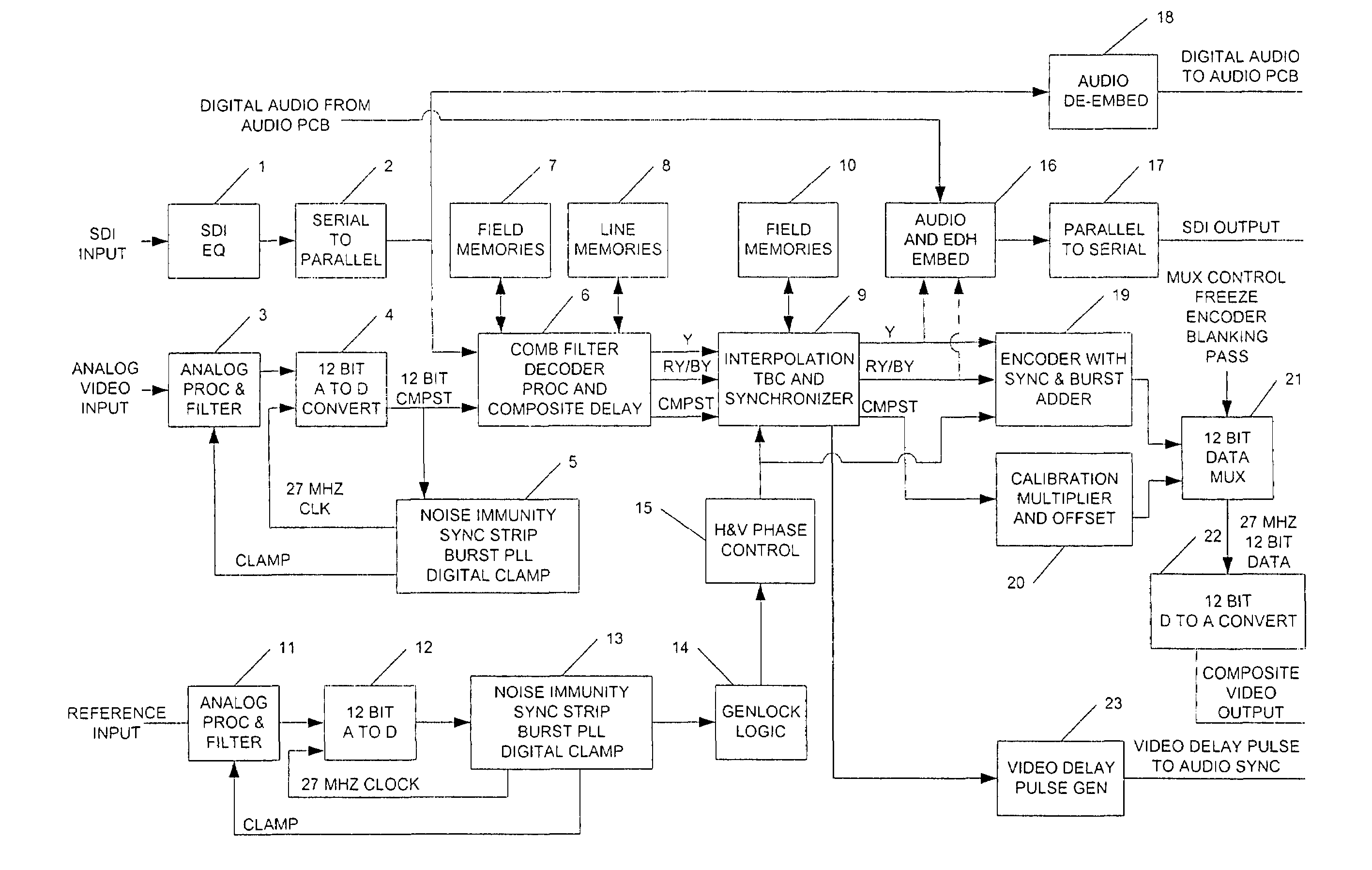
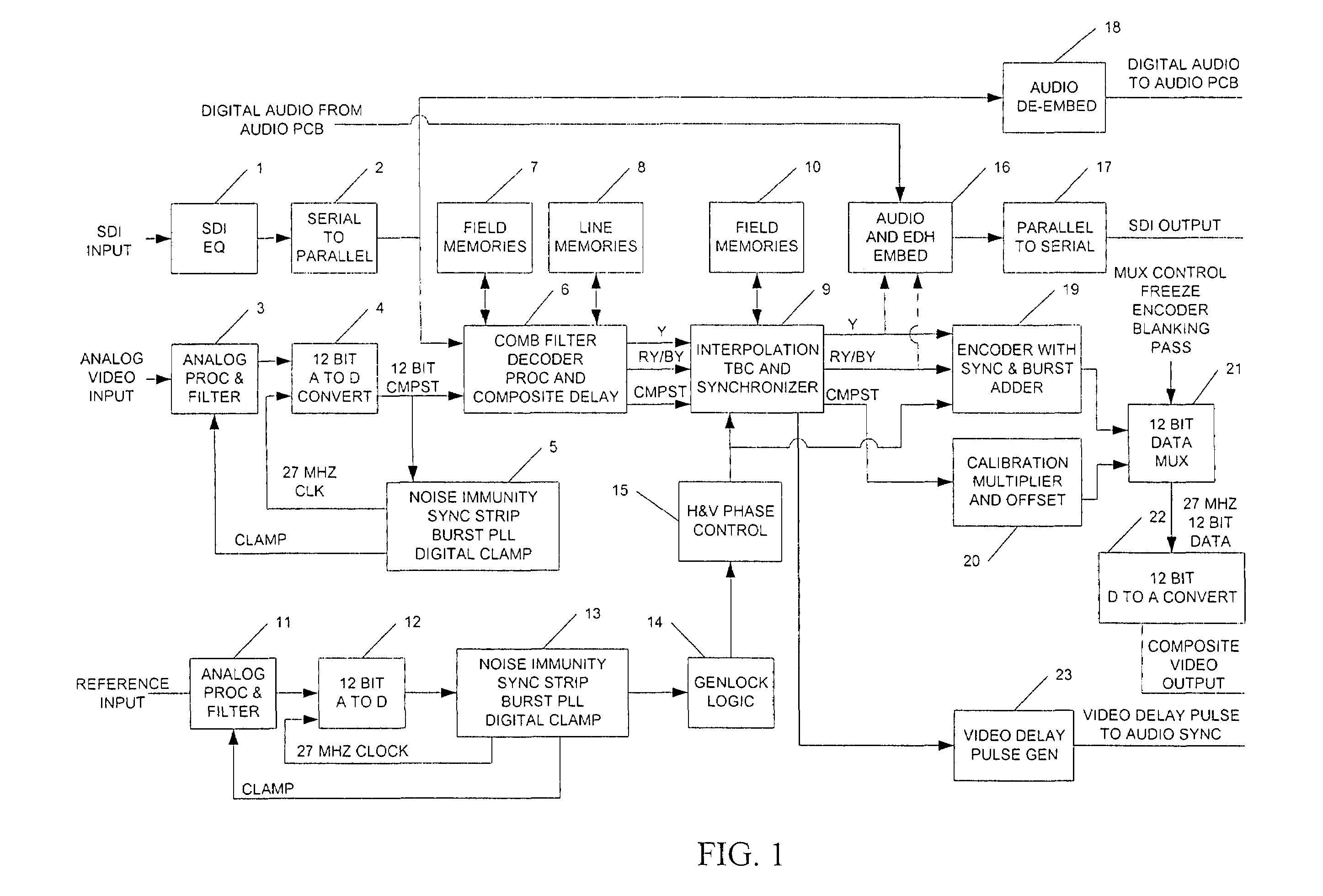
[0015]The unique aspect of this invention is the provision of parallel and coordinated synchronization paths for decoded and undecoded video. While simple, this provision is unique as is evidenced by the wide variety of competing products presently on the market that have no such provision or capability. The present invention coordinates the two synchronization paths and provides parallel control of the common synchronizer functions:[0016]1. Video Gain Control;[0017]2. Chroma Gain Control;[0018]3. Black Level Control;[0019]4. Hue Control;[0020]5. Image Position Control;[0021]6. SCH Phase Control;[0022]7. Genlock Coarse Phase Control;[0023]8. Genlock Fine Phase Control;[0024]9. Field and Frame Freeze;[0025]10. Hot Switch;[0026]11. Time Base Correction.

[0027]FIG. 1 illustrates a general block diagram of an exemplary embodiment of the invention. Block 1 represents a serial digital input receiver and equalizer. The SDI input normally conforms to the SMPTE 259 standard. Block 2 represent...


PUM


Abstract

A digital video synchronizer for providing parallel and coordinated synchronization paths for decoded and undecoded video. Processing is added for a parallel path in a synchronization memory that bypasses the comb filter and video decoder circuitry to allow a digitized composite video to pass through unchanged. This parallel path is coordinated with the decoder path to provide features of both a composite video synchronizer and a digital component decoder / synchronizer with time base corrector. A digital encoder transforms component video back into modulated composite video. The digital encoder generates a synchronizing and color burst signal to replace the sync and burst signals of the composite video signal. The synchronized composite and synchronized encoded signals are adjusted in timing, gain and DC offset to match one another so that the signals can be faded, mixed, or multiplexed without detectable differences. A multiplexer switches between the encoded version of the video signal and the undecoded version.

Description

CROSS-REFERENCE TO RELATED APPLICATIONS[0001]This application claims the benefit of U.S. Provisional Application No. 60 / 236,764 filed Sep. 29, 2000. This application is related to co-pending and commonly assigned patent applications “Composite Video Decoder”, Ser. No. 09 / 523,889, “Time Base Corrector”, Ser. No. 09 / 523,884, both filed Mar. 13, 2000, and “Digital Comb Filter”, Ser. No. 09 / 637,140, filed Aug. 11, 2000. Each co-pending patent application is hereby incorporated by reference into this description as fully as if here represented in full.BACKGROUND[0002]The present invention relates generally to an apparatus for synchronization of digital video and, more particularly, to a digital video synchronizer providing parallel and coordinated synchronization paths for decoded and undecoded video.[0003]For the processing of video signals to proceed without visible flaws, all signals must be precisely synchronized. The most important feature of this synchronization process is that it ...

Claims


Application Information

Patent Timeline
Patent Type & Authority Patents(United States)
IPC IPC(8): H04N11/00
CPCH04N5/0736
Inventor LOWE, VIRGIL L.
Owner FORTEL DTV
Why Eureka
Try Eureka