Laminated ceramic capacitor

a ceramic capacitor and laminated technology, applied in the field of laminated ceramic capacitors, can solve the problems of not meeting the level required for decoupling capacitors for high frequency circuits, generating too low esr, and unable to completely prevent esl from being generated in capacitors, etc., to achieve high capacitance without increasing the size and the number of processes of capacitors

Inactive Publication Date: 2006-05-16
SAMSUNG ELECTRO MECHANICS CO LTD
View PDF13 Cites 59 Cited by
  • Summary
  • Abstract
  • Description
  • Claims
  • Application Information

AI Technical Summary

Benefits of technology

[0021]The present invention has been made to solve the above problems, and it is an object of the present invention to provide a laminated ceramic capacitor, which can simultaneously satisfy requirements for ESL and ESR while having a high capacitance without increasing the size and the number of processes of the capacitor.

Problems solved by technology

However, with the constructions described above, the ESL cannot be completely prevented from being generated in the capacitor.
In particular, in the case of decoupling capacitors applied to high frequency circuits, since a small ESL can influence the decoupling capacitors, it is necessary to further reduce the ESL, and the problem of generating a too low ESR is still present.
According to the above disclosures, although the ESL can be further reduced in comparison to the laminated devices shown in FIGS. 2 and 3, the reduced amount of the parasitic impedance does not satisfy the level required for the decoupling capacitors for high frequency circuits.
However, according to the disclosure, there is a problem in that the ESL is increased.

Method used


Image

  • Laminated ceramic capacitor
  • Laminated ceramic capacitor
  • Laminated ceramic capacitor

Examples


first embodiment

[0058]First, FIGS. 4a and 4b are diagrams illustrating internal electrodes of a laminated ceramic capacitor according to the invention. Referring to FIGS. 4a and 4b, the laminated ceramic capacitor of the invention has first and second internal electrodes 41 and 42 vertically disposed adjacent to each other within the ceramic block 11, while allowing voltages having different polarities (such as a positive polarity and a negative polarity) to be applied thereto, respectively, and a plurality of withdrawing patterns 413 and 414; 423 and 424, which connect the first and second internal electrodes 41 and 42 to the external electrodes 12 and 13, respectively. As the first and second internal electrodes 41 and 42 are vertically adjacent to each other, and the voltages having different polarities are applied thereto, magnetic fluxes generated by high frequency current of the respective internal electrodes can be counterbalanced.

[0059]Additionally, each of the first and second internal ele...

third embodiment

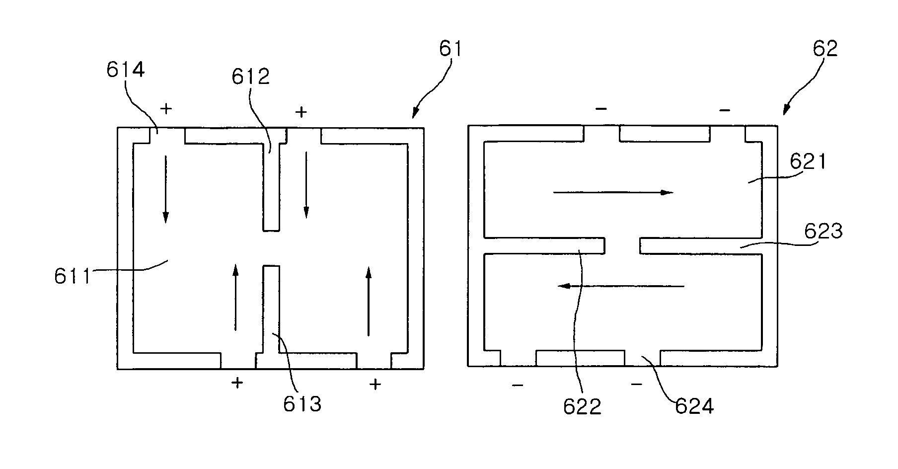
[0071]FIG. 6 is a diagram illustrating internal electrodes of a laminated ceramic capacitor according to the invention. Referring to FIG. 6, the laminated ceramic capacitor of the invention has first and second internal electrodes 61 and 62 vertically disposed adjacent to each other within the ceramic block 11, and a plurality of withdrawing patterns 614 and 624, which connect the first and second internal electrodes 61 and 62 to the external electrodes 12 and 13 having different polarities. The first and second internal electrodes 61 and 62 comprise a rectangular-shaped conductive pattern 611 and 621, and two slots 612 and 613; 622 and 623 extended from two lateral sides of the rectangular conductive pattern facing each other toward the center of the conductive pattern, respectively, thereby dividing some portion of the conductive pattern 611 and 621 from some other portion thereof.

[0072]The slots 612 and 613; 622 and 623 are collinear, and bisect the conductive patterns 611 and 62...

fourth embodiment

[0078]More specifically, as with the previously described embodiments, the laminated ceramic capacitor according to the invention has first and second internal electrodes 71 and 72 vertically disposed adjacent to each other within the ceramic block 11, and a plurality of withdrawing patterns 713 and 724, which connect the first and second internal electrodes 71 and 72 to the external electrodes 12 and 13 having different polarities, respectively. The first internal electrodes 71 comprise a rectangular conductive pattern 711, and a slot 712 extended between two lateral sides of the conductive pattern 711 facing each other so as to bisect the rectangular conductive pattern 711. The second internal electrode 72 comprises a rectangular conductive pattern 721, and two slots 723 and 722 extended from the two other lateral sides of the conductive pattern facing each other toward the center of the conductive pattern, respectively, to be perpendicular to the slot 712 of the first internal el...


PUM

PropertyMeasurementUnit
electricaaaaaaaaaa
conductiveaaaaaaaaaa
electric currentsaaaaaaaaaa

Abstract

A laminated ceramic capacitor includes a ceramic block formed by laminating a plurality of ceramic sheets, a plurality of external electrodes formed on outer surfaces of the ceramic block facing each other, and set as a positive terminal and a negative terminal, respectively, one or more first and second internal electrodes alternately arranged within the ceramic block such that electric currents flow in opposite directions in the internal electrodes, and a plurality of withdrawing patterns for connecting the first and second internal electrodes to the external electrodes, respectively.

Description

RELATED APPLICATIONS[0001]The present invention is based on, and claims priority from, Korean Application Number 2004-56255, filed Jul. 20, 2004, Korean Application Number 2004-87200, filed Oct. 29, 2004, and Korean Application Number 2005-16872, filed Feb. 28, 2005, the disclosures of which are incorporated by reference herein in their entirety.BACKGROUND OF THE INVENTION[0002]1. Field of the Invention[0003]The present invention relates to a laminated ceramic capacitor, and more particularly to a laminated ceramic capacitor, designed to realize a low equivalent series inductance (ESL) and a controllable equivalent series resistance (ESR) while realizing a high capacitance.[0004]2. Description of the Related Art[0005]A capacitor is a device for storing electricity, and is provided with two oppositely disposed electrode plates so that, when a voltage is applied to the capacitor, electric charges are accumulated in respective electrodes. When a direct voltage is applied to the capacit...

Claims


Application Information

Patent Timeline
Patent Type & Authority Patents(United States)
IPC IPC(8): H01G4/005H01G4/228
CPCH01G4/30H01G4/012
Inventor LEE, BYOUNG HWAPARK, DONG SEOKPARK, MIN CHEOLPARK, SANG SOOSHIM, CHANG HOONHWANG, KYUNG NAM
Owner SAMSUNG ELECTRO MECHANICS CO LTD
Why Eureka
Try Eureka