Method and VLSI circuits allowing to change dynamically the logical behavior

a technology of dynamic logical behavior and circuit, applied in the field of logically modifiable vlsi digital circuit, can solve problems such as occupying a large surface area of real estate, and achieve the effect of reducing manufacturing costs and high accuracy

Inactive Publication Date: 2006-05-16
IOAN DANCEA
View PDF19 Cites 57 Cited by
  • Summary
  • Abstract
  • Description
  • Claims
  • Application Information

AI Technical Summary

Benefits of technology

[0018]Advantageously, using a fixed hardware structure, the invention provides a mechanism for implementing a large number of VLSI digital circuits having each one a specified logical behaviour. This logical behaviour can be dynamically changed, without replacing the physical structure and / or without using any programming task. One basic cell with a particular physical structure is provided for implementing one product term of any combinational or synchronous sequential digital circuit. For changing the functions performed by the circuit, a set of weights uniquely defining the desired circuitry functions are calculated with high accuracy by an expert system and loaded in the registers of the basic cells. No testing of the logical structure realised with the VLSI circuit is necessary, and this significantly reduces manufacturing costs.

Problems solved by technology

In addition, for complex circuits the developer must add the logic part for testing the functional structure of the circuit, which takes a large surface of the real estate.

Method used


Image

  • Method and VLSI circuits allowing to change dynamically the logical behavior
  • Method and VLSI circuits allowing to change dynamically the logical behavior
  • Method and VLSI circuits allowing to change dynamically the logical behavior

Examples


Embodiment Construction

[0034]The following description is of preferred embodiments by way of example only and without limitation to combination of features necessary for carrying the invention into effect.

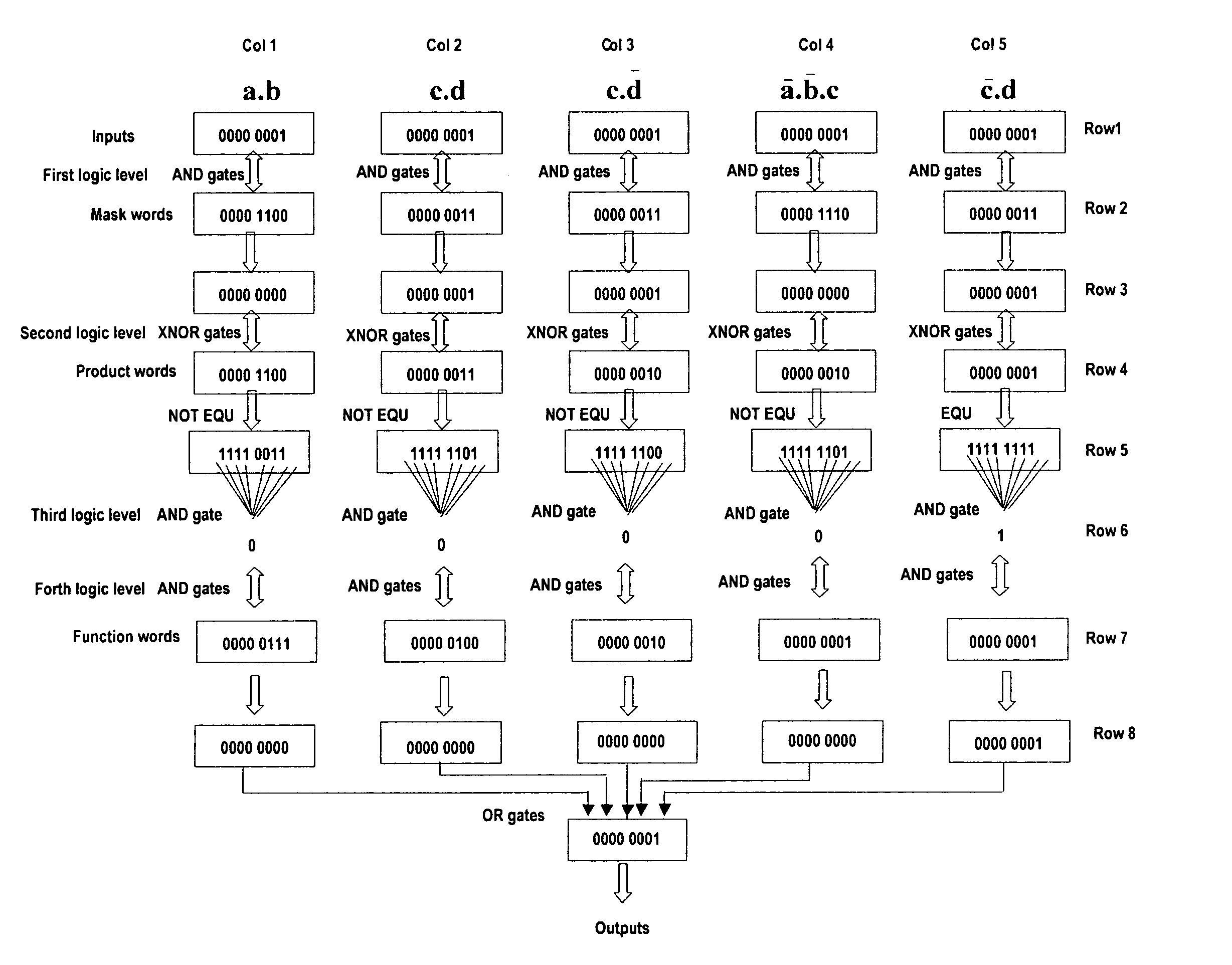
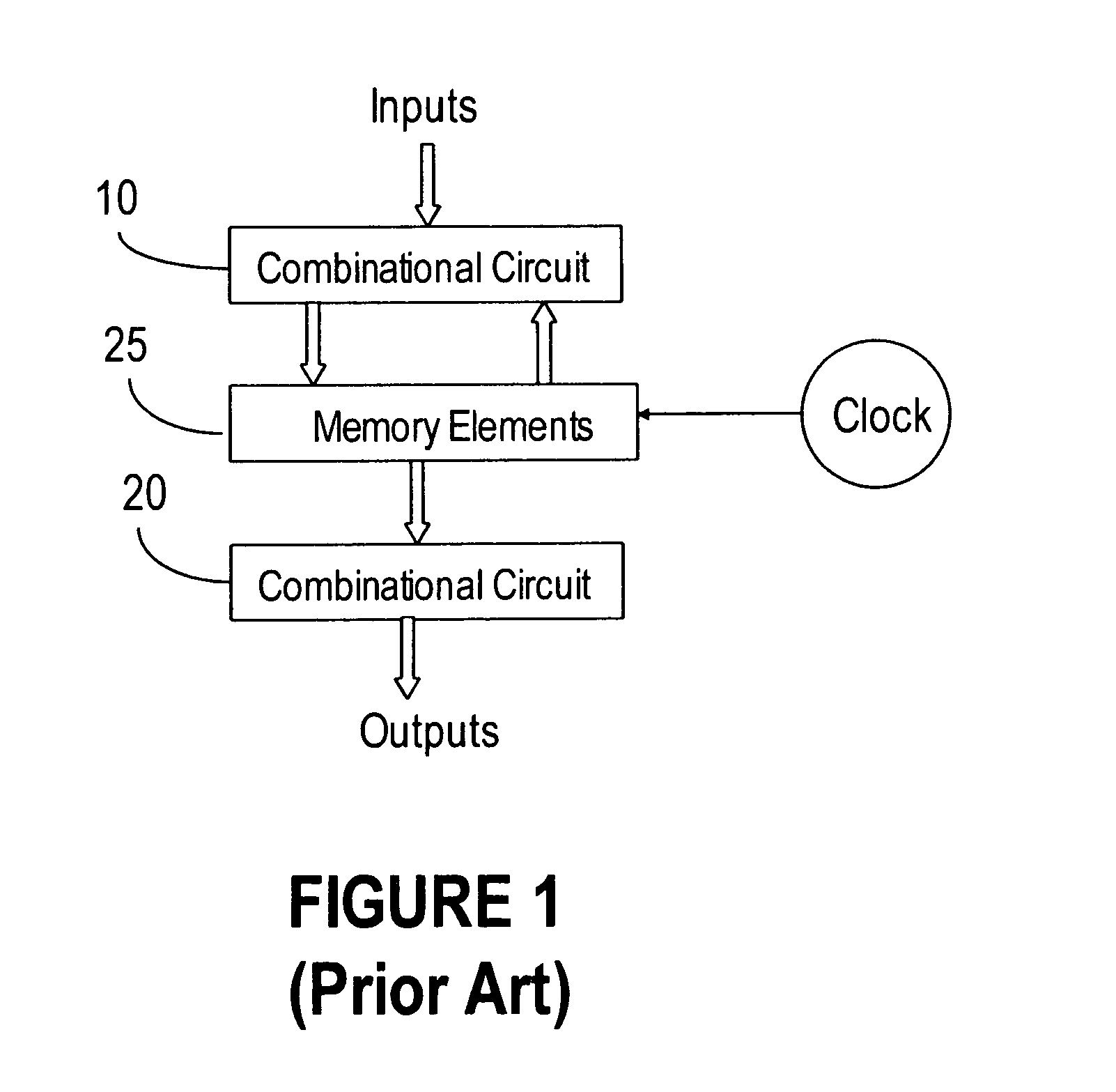
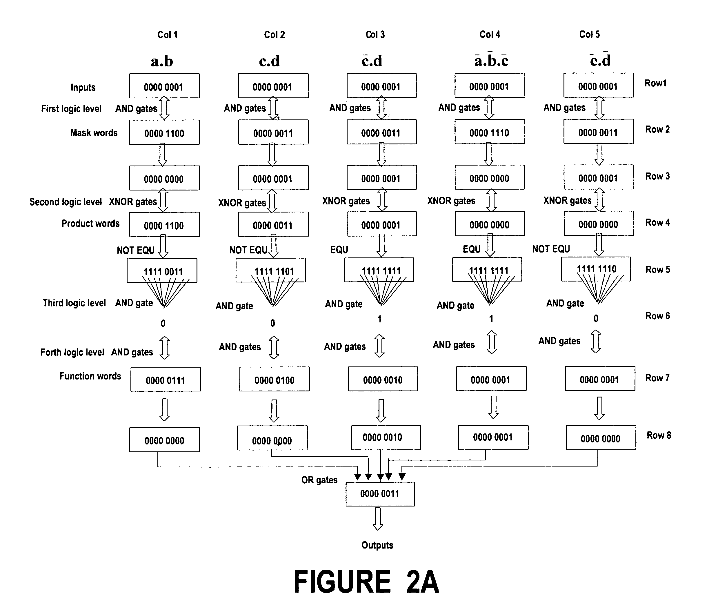
[0035]The present invention proposes a novel solution for implementing a combinational and / or synchronous sequential digital circuit, having a one and only one physical structure and able to implement a variety of sum-of-product functions. The method according to the invention is called the product terms method. More precisely it implements in hardware the general pattern of the sum-of-product form of a set of logical equations defining a multiple output combinational circuit, or the general pattern of the sum-of-product form of several sets of logical equations defining a synchronous sequential circuit. This is contrasting with the prior art solution, which uses direct implementation of equations by gates, to designate each logical circuit. To minimize the number of required gates of the circuit, it is ...


PUM


Abstract

A method, named the product terms method that allows to implement and / or to change dynamically the logical behavior of any combinational or synchronous sequential circuits has been presented. The method uses for every product term of logical equations, expressed as a sum-of-product, three memory words: mask word, product word and function word. The words of all product terms are ranged in a table, which characterize the logical behavior of the circuit.The invention provides the hardware structure of several new types of VSLI circuits, having re-configurable logic behaviors. A first embodiment implements any type of multiple output combinational circuit, a second embodiment implements any synchronous sequential circuit with only clock input and, a third embodiment implements any synchronous sequential circuit s with data inputs and clock input.An expert system capable to generate the tables used for the product terms method by interpreting and analysing the logical equations either supplied by the user or found in a database is also provided.

Description

BACKGROUND OF THE INVENTION[0001]1. Field of Invention[0002]This invention is directed to logically modifiable VLSI digital circuits, and more specifically to combinational and synchronous sequential circuits that may be dynamically configured and re-configured to perform a digital function of choice.[0003]2. Related Art[0004]Digital circuits are realised with integrated circuits. An integrated circuit, called chip, contains electrical components such as transistors, diodes, resistors and capacitors. The various components are interconnected inside the chip to form gates and memory elements.[0005]A combinational circuit (CC) is obtained using exclusively elementary gates (NOT, OR, AND, XOR, NOR, etc.). Each combinational circuit have a hardware structure designed to perform definite functions, as specified by logical equations. Consequently, there is a specific hardware structure for a 3 to 8 decoder, another hardware structure for a 4 bits comparator, and so on.[0006]Sequential cir...

Claims


Application Information

Patent Timeline
Patent Type & Authority Patents(United States)
IPC IPC(8): G06F7/60G06F7/38G06F17/50H03G5/00
CPCH03G5/005G06F17/5054G06F30/34
Inventor DANCEA, IOAN
Owner IOAN DANCEA
Why Eureka
Try Eureka