
Frequency converter

a frequency converter and converter technology, applied in the field of frequency converters, can solve the problems of increasing circuit size and power consumption, increasing power consumption, and not being able to suppress aliasing as intended, and achieve the effect of increasing power consumption, improving frequency step (frequency resolution) p times

Inactive Publication Date: 2006-05-16
SAMSUNG ELECTRONICS CO LTD
View PDF9 Cites 18 Cited by
  • Summary
  • Abstract
  • Description
  • Claims
  • Application Information

AI Technical Summary

Benefits of technology

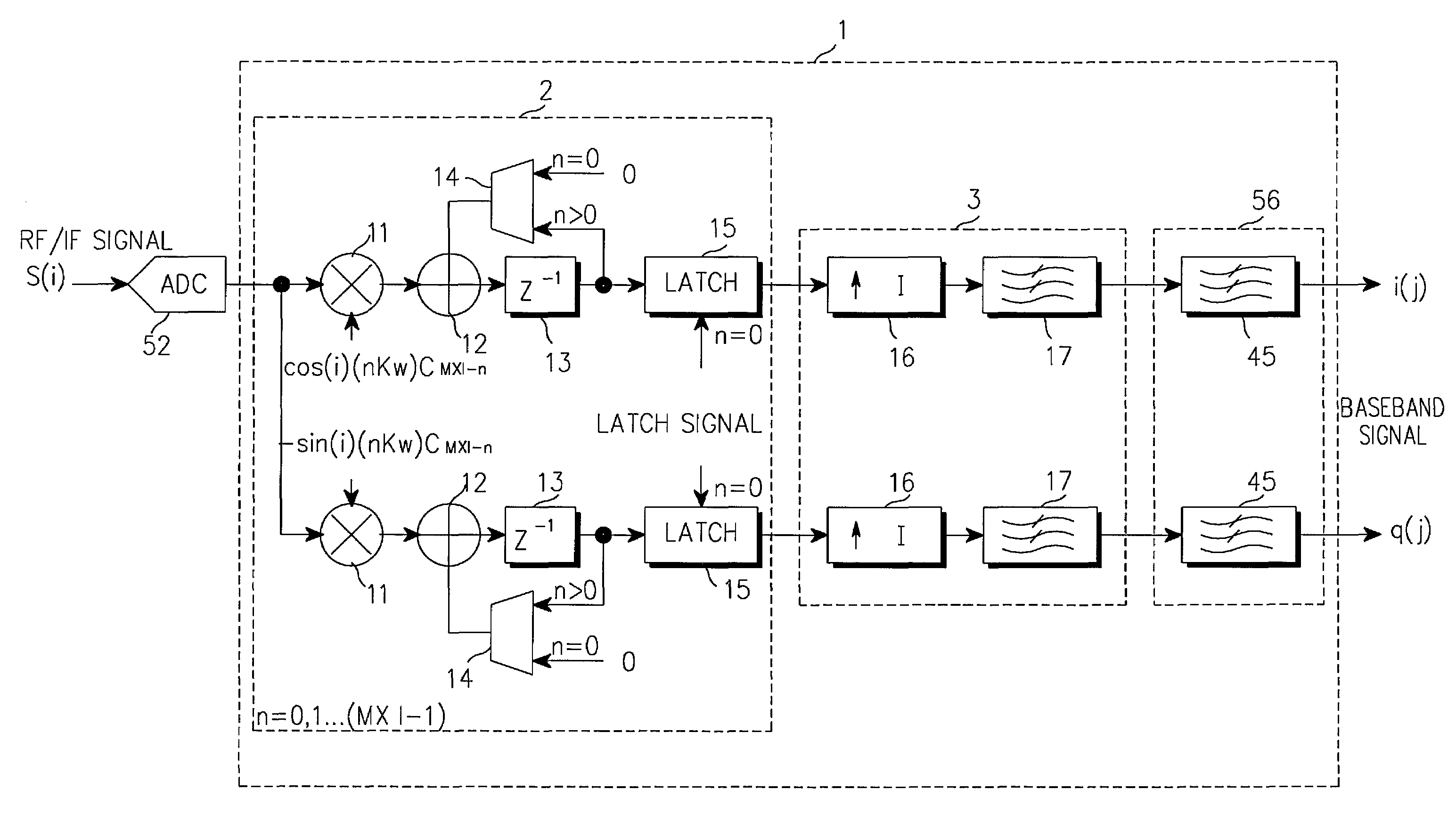
[0010]Therefore, the present invention has been made in view of the above problems, and it is an object of the present invention to provide a frequency converter with an excellent frequency characteristic, having a reduced number of multipliers.
[0012]By sharing multipliers used for frequency conversion and a filter based on the polyphase structure, it is possible to realize a frequency converter having a reduced number of multipliers and also having a filter function, a frequency conversion function, and a sampling frequency conversion function.
[0021]In this manner, the frequency converter improves its frequency step (frequency resolution) P times without changing the number of samplings and operations, and without an increase in power consumption.

Problems solved by technology

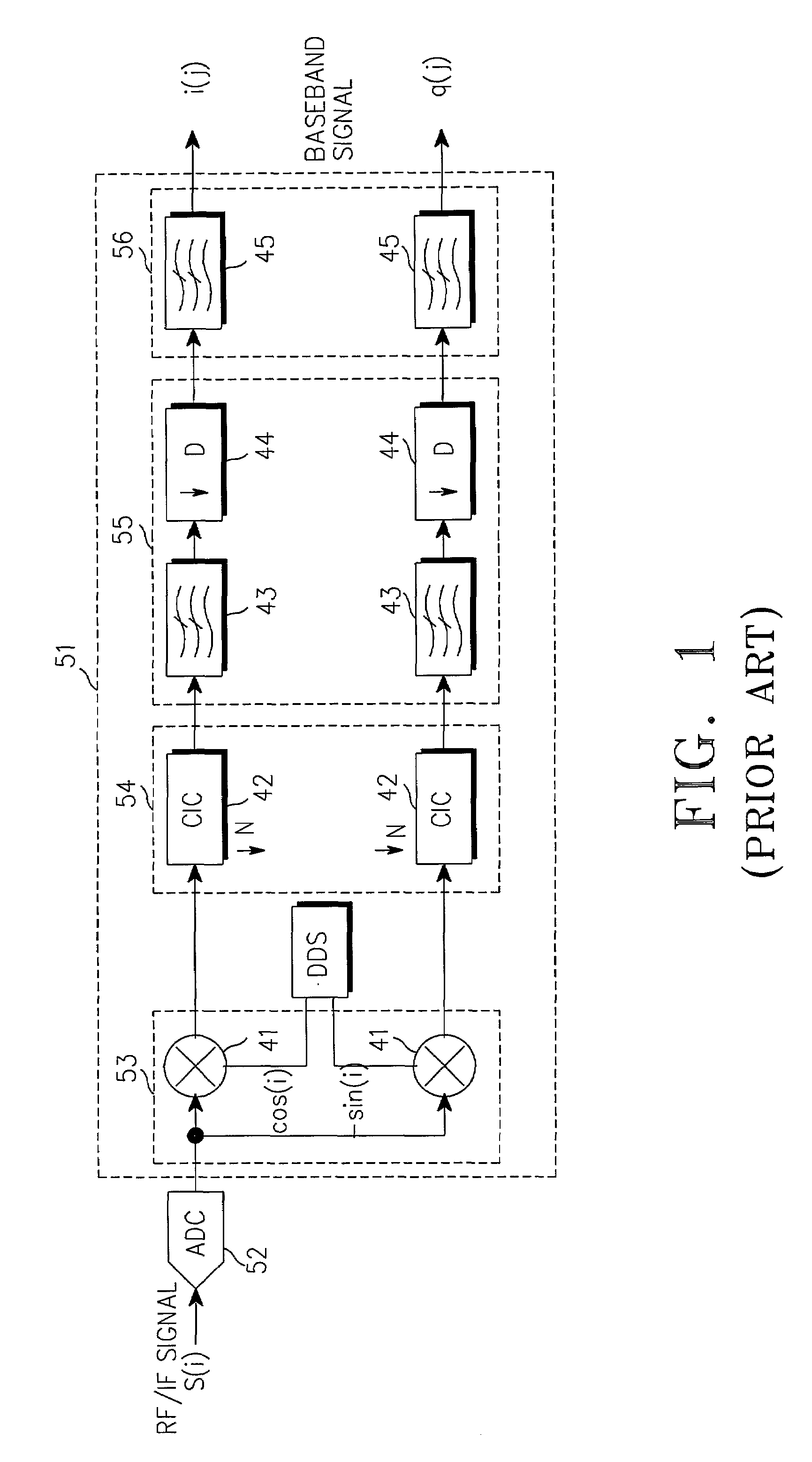
A general multiplier-based filter requires a plurality of multipliers, causing an increase in circuit size and power consumption.
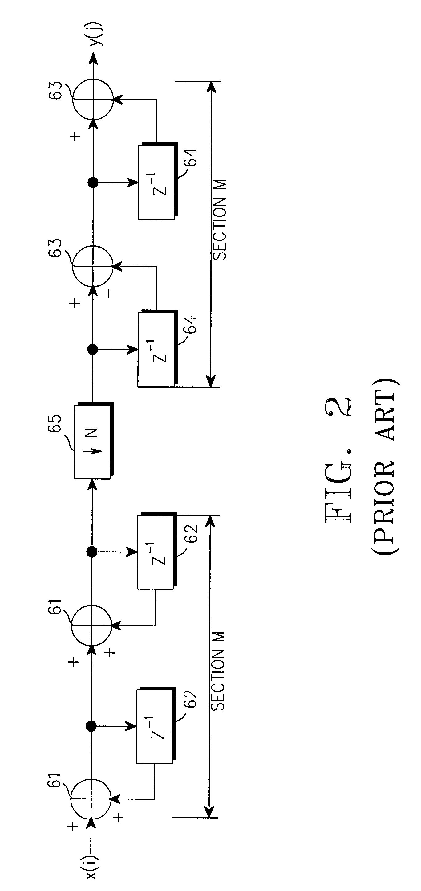
The CIC filter-based digital down-converter can suppress aliasing without using multipliers, but the pass band characteristic of the filter is not smooth.
However, an expansion of the pass band deteriorates a rejection band characteristic of the filter, making it impossible to suppress the aliasing as intended.

Method used


Image

  • Frequency converter
  • Frequency converter
  • Frequency converter

Examples


embodiment 1

[0050]A frequency converter according to a first embodiment of the present invention will be described with reference to FIGS. 6 and 7. FIG. 6 is a block diagram illustrating a circuit structure of a digital down-converter according to the first embodiment of the present invention, and FIG. 7 illustrates a frequency characteristic of an input / output signal of the digital down-converter. This embodiment provides a structure of polyphase filters having one coefficient calculated by dividing M×I coefficients by M×I, in which multipliers for the polyphase filters are arranged to be common to respective phases of the polyphase filters and to change ROM (Read Only Memory) data comprised of filter coefficients and sine wave data at every phase.

[0051]Referring to FIG. 6, a digital down-converter 1 according to the first embodiment of the present invention includes a decimator / mixer 2, an interpolator 3 and a channel filter 56. The decimator / mixer 2 performs quadrature conversion (quadrature...

embodiment 2

[0054]Next, a frequency converter according to a second embodiment will be described with reference to FIG. 8. FIG. 8 is a block diagram illustrating a circuit structure of a digital up-converter according to the second embodiment of the present invention. This embodiment provides a polyphase filter having two coefficients obtained by dividing 2×M2 coefficients by M2, in which multipliers and delays for the polyphase filters are arranged to be common to respective phases of the polyphase filters and to change ROM data comprised of filter coefficients and sine wave data at every phase.

[0055]Referring to FIG. 8, a digital up-converter 4 according to the second embodiment of the present invention includes an interpolator 5 and an interpolator / mixer 6. The interpolator 5 is comprised of M1-fold up-samplers 21 and lowpass filters 22, and performs M1-fold interpolation on received complex signals i(j) and q(j). The interpolator / mixer 6 performs frequency conversion by a frequency Kω, M2-f...

embodiment 3

[0057]Next, a frequency converter according to a third embodiment will be described with reference to FIG. 9. FIG. 9 is a block diagram illustrating a circuit structure of a digital up-converter according to the third embodiment of the present invention. This embodiment provides a polyphase filter having two coefficients obtained by dividing 2×(M×D) coefficients by M×D, in which multipliers and delays for the polyphase filters are arranged to be common to respective phases of the polyphase filters and to change ROM data comprised of filter coefficients and sine wave data at every phase.

[0058]Referring to FIG. 9, a digital up-converter 7 according to the third embodiment of the present invention includes a decimator 8 and an interpolator / mixer 9. The decimator 8 is comprised of lowpass filters 29 and 1 / D-fold down-samplers 30, and performs 1 / D-fold decimation on received complex signals i(j) and q(j). The interpolator / mixer 9 performs frequency conversion by a frequency Kω, (M×D)-fol...


PUM


Abstract

Disclosed is a frequency converter with an excellent frequency characteristic, having a minimized number of multipliers. A digital down-converter includes a decimator / mixer, an interpolator and a channel filter. The decimator / mixer performs quadrature conversion from a real signal to complex signals, frequency conversion by a frequency Kω, and 1 / (M×I)-fold decimation on a signal obtained by sampling an RF / IF signal S(i) by an A / D converter. The interpolator is comprised of I-fold up-samplers and lowpass filters, and performs I-fold interpolation on the outputs from the decimator / mixer. The channel filter is comprised of lowpass filters having a band characteristic given to a communication channel, and outputs band-rejected baseband signals i(j) and q(j) by filtering the outputs of the interpolator.

Description

PRIORITY[0001]This application claims priority to an application entitled “Frequency Converter” filed in the Japanese Patent Office on Mar. 2, 2001 and assigned Serial No. 2001-58396, the contents of which are hereby incorporated by reference.BACKGROUND OF THE INVENTION[0002]1. Field of the Invention[0003]The present invention relates generally to a frequency converter for converting a frequency of an input signal by digital signal processing, and in particular, to a frequency converter with an excellent frequency characteristic, capable of converting a sampling frequency.[0004]2. Description of the Related Art[0005]A conventional frequency converter includes a digital down-converter (DDC) and a digital up-converter (DUC). The digital down-converter A / D (Analog-to-Digital)-converts a received RF / IF (Radio Frequency / Intermediate Frequency) signal, and then down-converts the A / D-converted signal to a baseband or demodulation IF signal by digital signal processing. The digital up-conve...

Claims


Application Information

Patent Timeline
IPC IPC(8): G06F17/10H03H17/06
CPCH03H17/0275H03H17/0664H03H17/0657
Inventor KISHI, TAKAHIKO
Owner SAMSUNG ELECTRONICS CO LTD
Learn More