Rapid catalyst warm-up control device for internal combustion engine

a technology of control device and catalyst, which is applied in the direction of electrical control, machines/engines, mechanical apparatus, etc., can solve the problems of insufficient oxidation reaction of rich components in the catalyst, inability to efficiently mix rich and lean gases in the catalyst, etc., to achieve rapid catalyst warm-up, reduce exhaust gas emission, and improve rapid catalyst warm-up performance

Inactive Publication Date: 2006-05-23
DENSO CORP +1
View PDF8 Cites 11 Cited by
  • Summary
  • Abstract
  • Description
  • Claims
  • Application Information

AI Technical Summary

Benefits of technology

[0010]The present invention has been made in view of the foregoing. Accordingly, it is an object of the present invention to provide a rapid catalyst warm-up control device for an internal combustion engine. The control device is capable of warming up the catalyst by performing injection dither while preventing rich components in the catalyst from slipping through the catalyst even during the period when the catalyst temperature is still low, such as the case immediately after starting the engine, and permits realization of both the decrease of exhaust gas emission immediately after the start-up and improvement in rapid catalyst warm-up performance. The control facilitates the mixing of the rich and lean gases to accelerate the oxidation reaction of the rich components in the catalyst.
[0014]According to the present invention, this problem is overcome by performing irregular injection dither control for switching injection modes between lean and rich injection modes in such a pattern that rich injections do not occur consecutively for the same cylinder. In this manner, rich gas emitted from the cylinder after rich injection is permitted to flow through a different region in the catalyst (where lean gas has been flowing till then) instead of flowing through the same limited region and hence it is possible to mix rich and lean gases efficiently in the catalyst. Consequently, even during a period when catalyst temperature is low, such as immediately after start-up of the engine, injection dither can be performed in an early stage to warm up the catalyst, while accelerating the oxidation reaction of rich components in the catalyst to prevent the pass-through of the rich components. It is thus possible to realize both, a decrease of exhaust gas emission immediately after start-up of the engine, and improvement in rapid catalyst warm-up performance.
[0015]According to a second aspect of the invention, lean injection is preferably performed first when starting the irregular injection dither control. By doing so, when the irregular injection dither control is started, rich gas can be introduced into the catalyst where lean gas has been already introduced by the lean injection previously performed. In this manner, a reliable mixture of lean and rich gases in the catalyst can be ensured from the very first rich injection after starting the irregular injection dither control. This also makes it possible to prevent the rich components from slipping through the catalyst from the very first rich injection.
[0016]Further, according to a third aspect of the present invention, a larger number of lean injections may be performed than rich injections during the irregular injection dither control. By doing so, since rich gas can be mixed with lean gas more efficiently, oxidation reaction of the rich components can be accelerated further and the pass-through of the rich components can be prevented more reliably.
[0017]Further, according to a fourth aspect of the present invention, ignition timing for a cylinder for which a rich injection is to be performed may be retarded during the irregular injection dither control. By doing so, the temperature of the rich gas emitted from the cylinder for which the rich injection has been performed can be raised by the ignition timing retarding to make it possible to accelerate the oxidation reaction of the rich components in the catalyst and to more reliably prevent the pass-through of the rich components. If the extent of the ignition timing retardation is made larger, the rich gas temperature can be raised further to cause after-burning of exhaust gas in the exhaust pipe upstream of the catalyst, and thus the effects of rapidly warming up the catalyst can be further enhanced by the heat of the after-burning.

Problems solved by technology

Therefore, if the injection dither control is performed in such a cycle that rich injection occurs consecutively for the same cylinder, rich gas emitted from the corresponding cylinder after every rich injection will flow through a same limited region in the catalyst and hence it becomes impossible to efficiently mix rich and lean gases in the catalyst.
Accordingly, oxidation reaction of rich components cannot be accelerated enough in the catalyst during the period when catalyst temperature is low immediately after starting of the engine.

Method used


Image

  • Rapid catalyst warm-up control device for internal combustion engine
  • Rapid catalyst warm-up control device for internal combustion engine
  • Rapid catalyst warm-up control device for internal combustion engine

Examples


Embodiment Construction

[0028]The following description of the preferred embodiments is merely exemplary in nature and is in no way intended to limit the invention, its application, or uses.

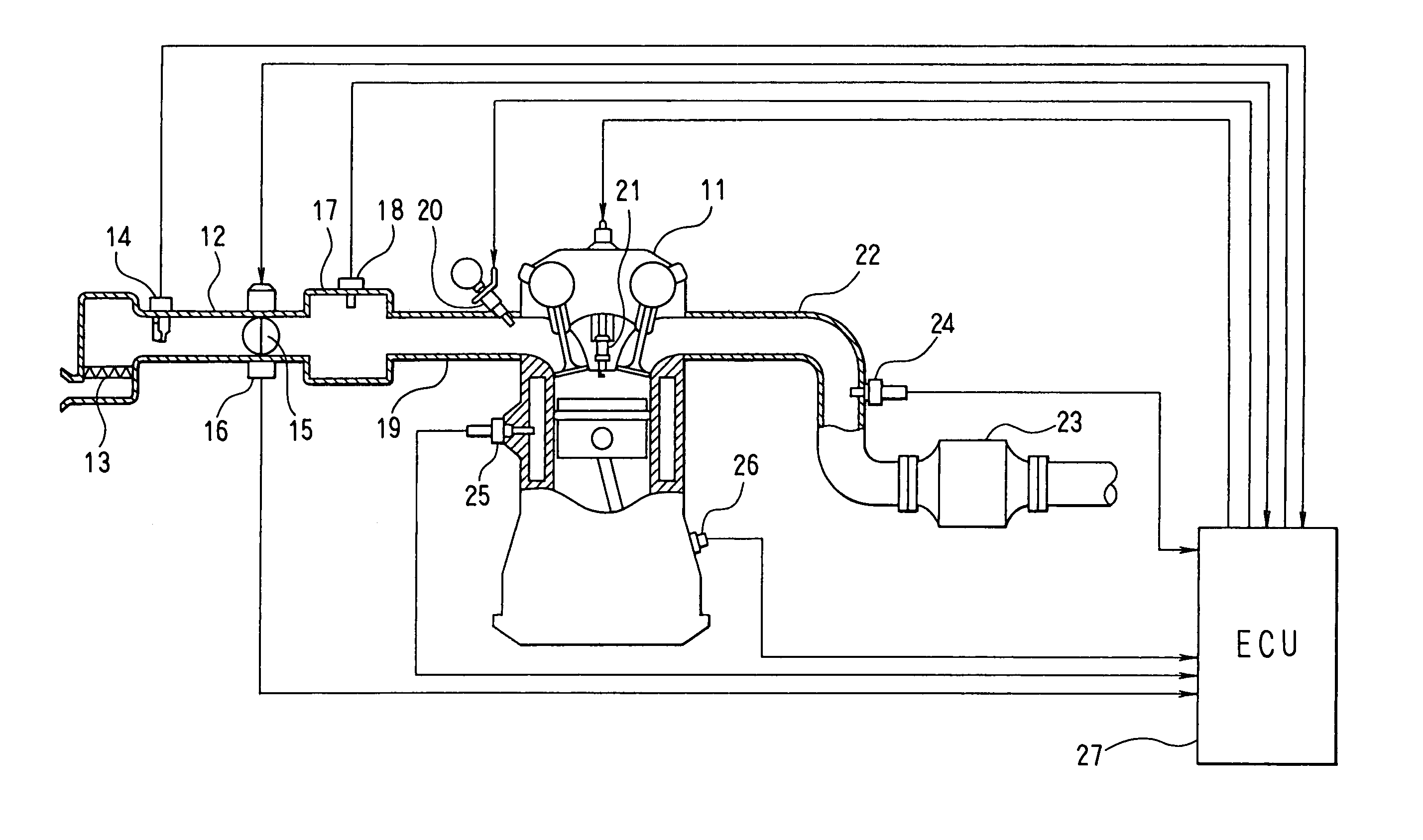
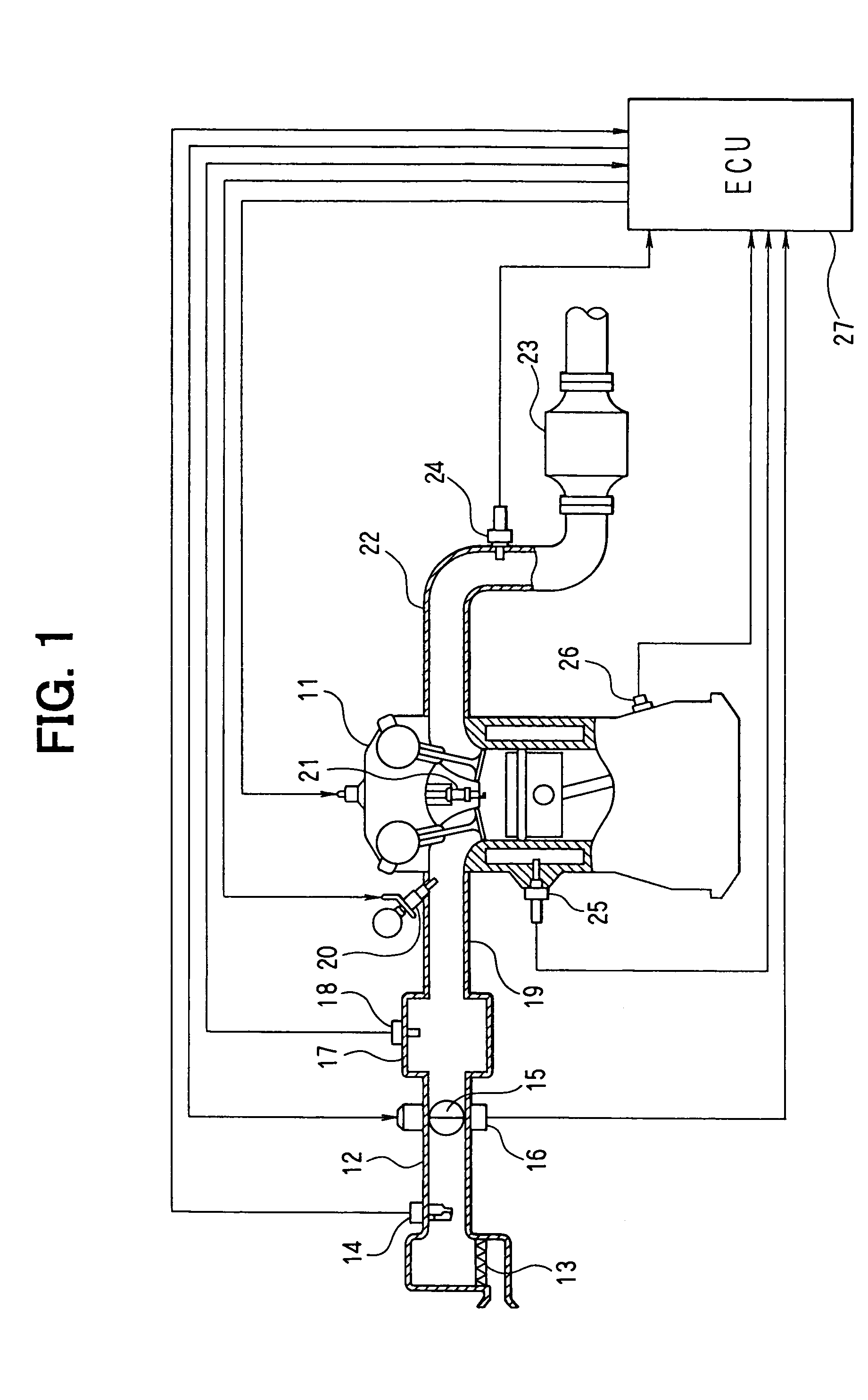
[0029]An embodiment of the present invention will now be described with reference to the drawings. First, the schematic structure of an entire engine control system will be described based on FIG. 1. An in-line 4-cylinder engine 11 constituting the internal combustion engine has four cylinders, a first cylinder #1 to a fourth cylinder #4. An air cleaner 13 is provided at the most upstream portion of an intake pipe 12 of the engine 11, and an air flow meter 14 is provided downstream of the air cleaner 13 for detecting an intake air amount. At the downstream side of the air flow meter 14, there are provided a throttle valve 15 whose opening degree is adjusted by a DC motor or the like and a throttle opening sensor 16 for detecting a throttle opening degree.

[0030]Further, a surge tank 17 is provided downstream of the throt...


PUM


Abstract

A rapid catalyst warm-up control device for an internal combustion engine performs irregular injection dither control during the rapid catalyst warm-up control after starting the engine. In the irregular injection dither control, injection modes are switched after every fuel injection to the cylinders (every 180° CA for a 4-cylinder engine) between a lean injection mode and a rich injection mode in such a pattern that rich injections will not occur consecutively for the same cylinder (dither cycle=540° CA, 900° CA, 1080° CA, or the like). In the lean injection mode, fuel is injected such that the air-fuel ratio is leaner than the stoichiometric ratio, and in the rich injection mode, air-fuel ratio is richer than the stoichiometric ratio. The rich gas emitted from the cylinders where the rich injection has been performed is thus allowed to flow through a different catalyst region every time instead of flowing only through the same region.

Description

CROSS REFERENCE TO RELATED APPLICATIONS[0001]This application is based upon, claims the benefit of priority of, and incorporates by reference Japanese Patent Application No. 2003-151933 filed May 29, 2003.BACKGROUND OF THE INVENTION[0002]1. Field of the Invention[0003]The present invention relates to a rapid catalyst warm-up control device for rapidly warming up a catalyst used for purifying exhaust gas from an internal combustion engine.[0004]2. Description of the Related Art[0005]In recent years, vehicles having an internal combustion engine have been provided with a catalyst such as three way catalyst for purifying exhaust gas from the internal combustion engine. In such systems, since the exhaust gas purification ratio of the catalyst remains low until the catalyst is warmed up to active temperature after starting the engine, measures are taken to rapidly warm up the catalyst. This is done by performing rapid catalyst warm-up control until the catalyst reaches its active tempera...

Claims


Application Information

Patent Timeline
Patent Type & Authority Patents(United States)
IPC IPC(8): F01N3/00F02D41/06F02D41/02F02D41/14
CPCF02D41/0255F02D41/1408Y02T10/26Y02T10/12
Inventor TANAKA, TOSHIHIKOHOSHI, KOICHIITOH, TAKAAKI
Owner DENSO CORP
Why Eureka
Try Eureka