Solar charged, electrically driven watercraft

a solar-powered, electrically driven technology, applied in the field of solar-powered pontoon boats, can solve the problems of electric boats not being able to compete with gasoline engines, environmental damage to the very waters and ecosystems, and electric boats still present engineering challenges, so as to reduce the effect of water forces on the craft, reduce water friction and wake, and stabilize the cra

Inactive Publication Date: 2006-05-23
LITTLE ROLLAND N
View PDF21 Cites 46 Cited by
  • Summary
  • Abstract
  • Description
  • Claims
  • Application Information

AI Technical Summary

Benefits of technology

[0030]According to the present invention, an electrically driven, solar charged watercraft includes a pontoon section, a strut section, a deck section, and a solar canopy section. The canopy section comprises a headliner layer and a solar panel layer, spaced by a ventilation area. The solar canopy may further comprise a ventilation system having a fan, a thermostatic switch, a photocell, air inlet ports, and air exhaust ports. The aft section of the pontoon, moreover

Problems solved by technology

Eventually, the state of the art was such that electric engines could not compete with gasoline engines.
Unfortunately, the success of gasoline powered boating has brought environmental damage to the very waters and ecosystems that support the enterprise.
Electric boats, however, still present engineering challenges.
Electric boat motors consume large amounts of DC power to move a load over water.
The weaknesses in the present state of the art of electric boats are becoming evident as interest in their use increases:(1) They require the use of AC electrical wires on or near the water for recharging;(2) The battery housing area provides potential

Method used


Image

  • Solar charged, electrically driven watercraft
  • Solar charged, electrically driven watercraft
  • Solar charged, electrically driven watercraft

Examples


Embodiment Construction

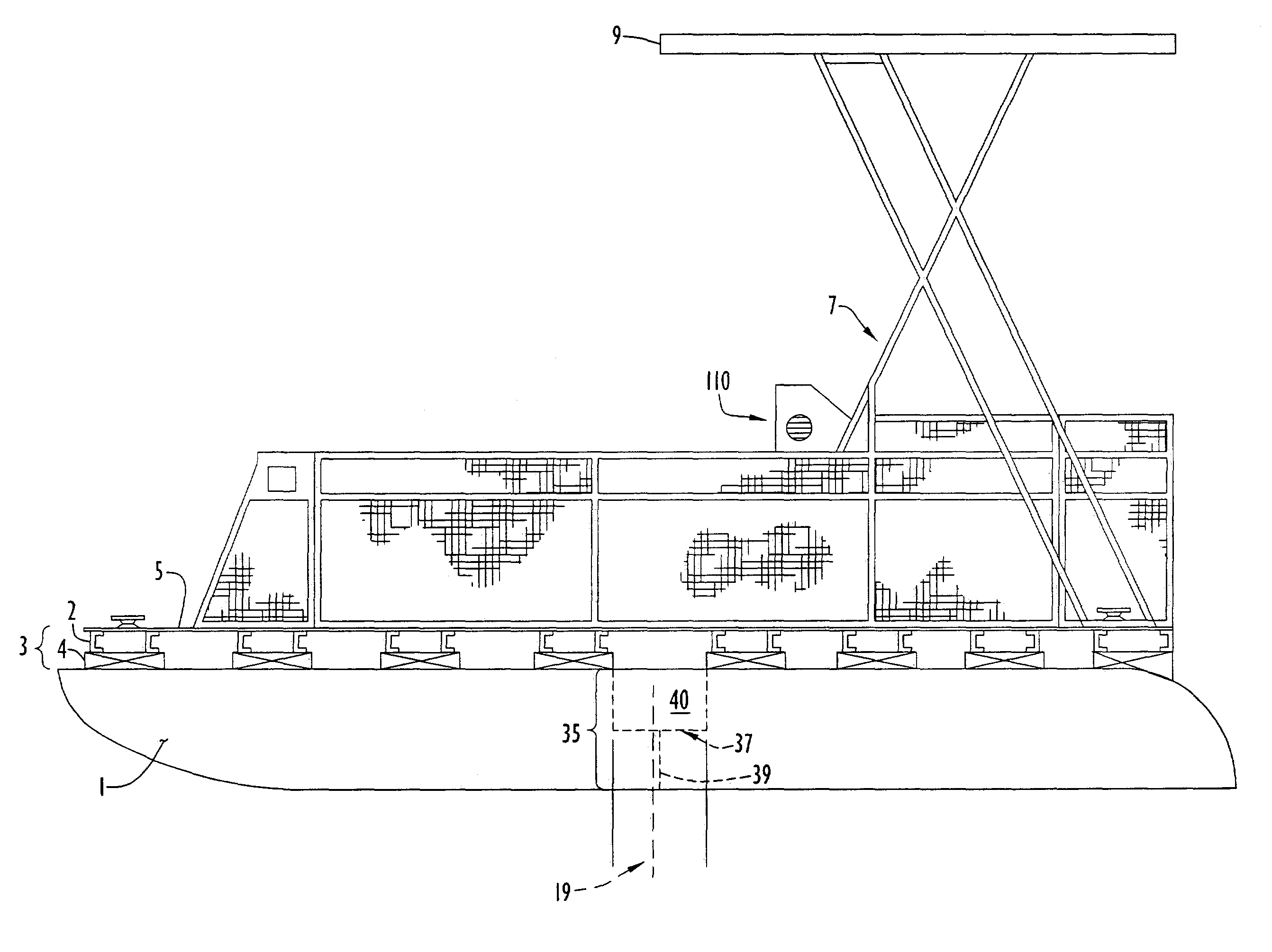
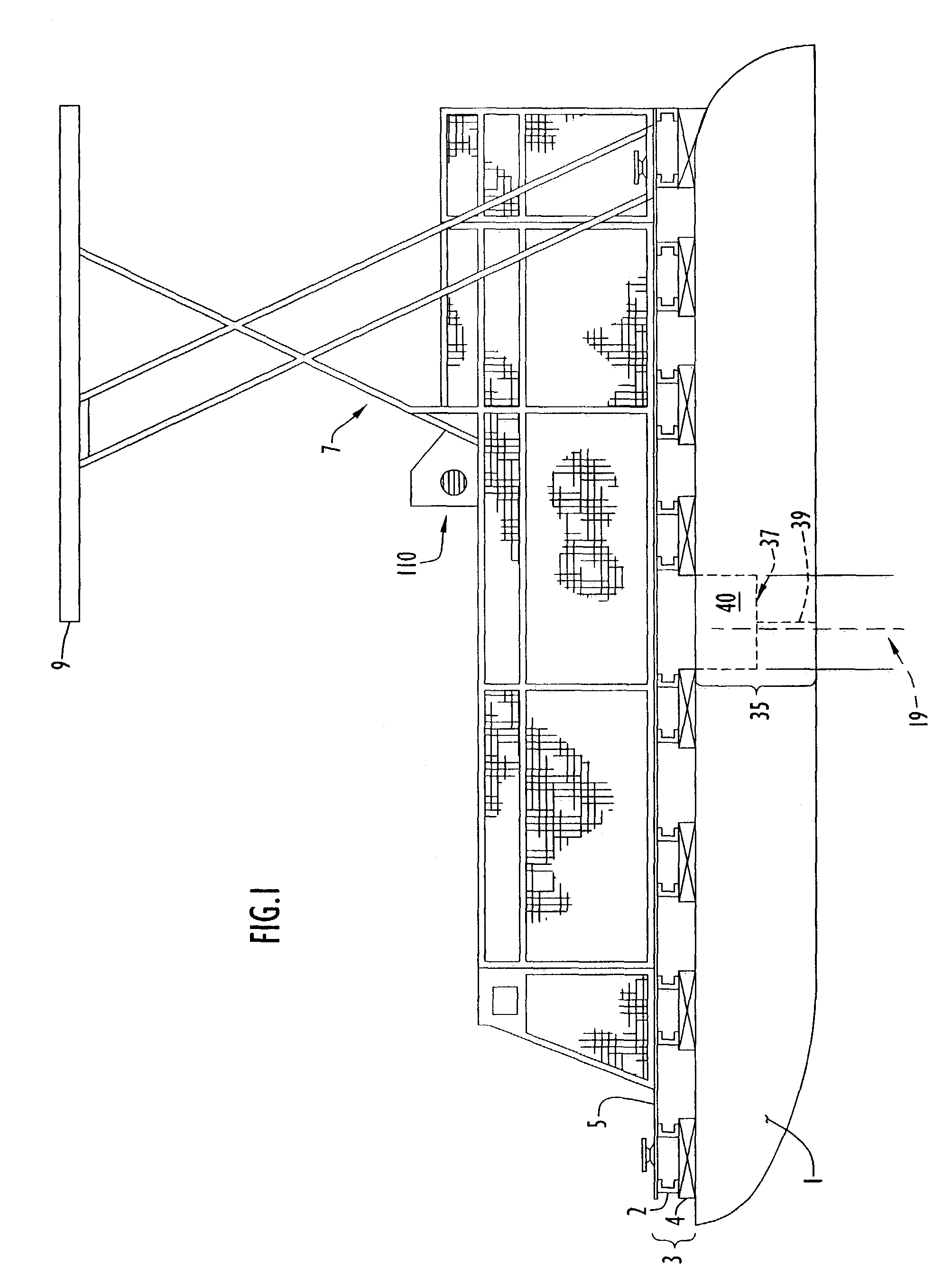
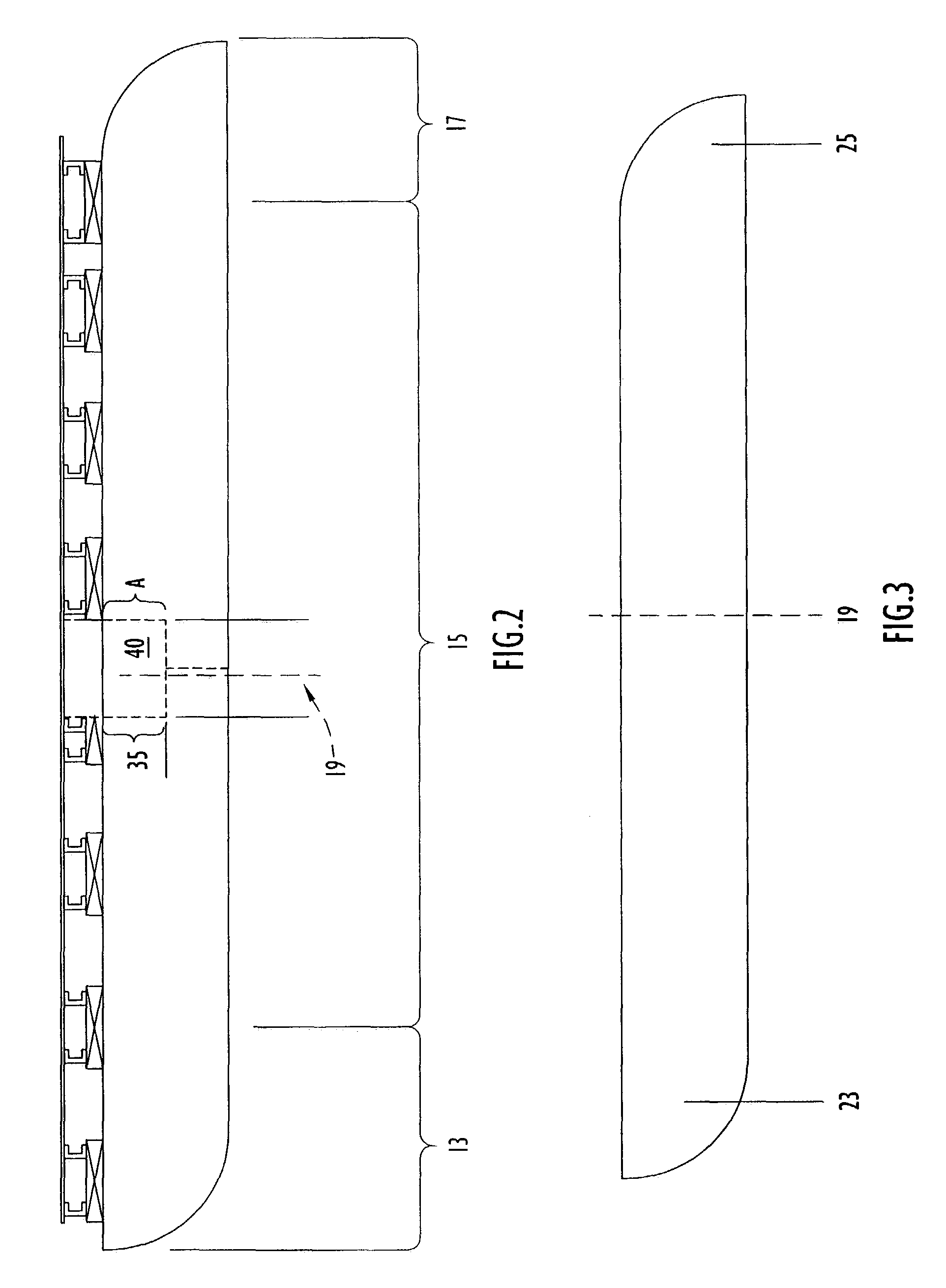
[0059]The electric watercraft of the instant invention is shown in FIG. 1. Generally, the watercraft generally comprises a pontoon section 1 secured beneath a craft body including a deck section 5 by means of a strut section 3 including multiple spaced joists 2 and brackets 4. The strut section may further include a motor mounting bracket (not shown). In the embodiment shown: in the figure, the pontoon section 1 further comprises a battery box 40 located in battery bay 35. Supporting plates 37, 39, support the battery box 40 in a position about the pontoon center of flotation 19. A control console 110 is located on the deck 5. A solar canopy 9 including a ventilation system is supported above the deck 5 using a canopy supporting means 7. The supporting means 7 is conventional in the art and typically comprises a lightweight metal such as aluminum, but other coated or uncoated metals (e.g., chrome or stainless steel) may be used. A particularly preferred embodiment comprises hollow a...


PUM


Abstract

A solar powered watercraft including a pontoon section, a strut section, a deck section, and a solar canopy section is provided. The canopy section comprises a headliner layer, a ventilation space, and means for receiving solar radiation. The solar canopy may further comprise a means for flowing air through the ventilation space that includes a fan, a thermostatic switch, a photocell, air inlet ports, and air exhaust ports. The aft section of the pontoon, moreover, may possess a dual tapered design that reduces water friction and wake. The watercraft further includes means for containing a battery pack that, in turn, comprises means for removing heat and gaseous byproducts from the containing means. The containing means is either made integral with the pontoon or is attached to the pontoon's outer surface. The watercraft may possess an aft-oriented trim, which stabilizes the craft and reduces the effect of water forces.

Description

CROSS REFERENCE TO RELATED APPLICATIONS[0001]This application claims priority from U.S. Provisional Patent Application Ser. No. 60 / 390,127, entitled “Solar Boat Cooling and Exhaust System” and filed Jun. 21, 2002. The disclosure of the above-mentioned provisional application is incorporated herein by reference in its entirety.BACKGROUND OF THE INVENTION[0002]1. Technical Field[0003]The present invention pertains to a cooling and exhaust system for boats. In particular, the present invention pertains to a cooling and exhaust system for a solar-powered pontoon boat.[0004]2. Discussion of the Related Art[0005]U.S. Pat. No. 5,131,341 (Newman) discloses a system for distributing electric power on a sailing ship using arrays of photovoltaic cells covering the ship's sails and rigging to generate electric power during daylight for the purpose of driving a ship's screw. The solar array electric power output is processed by a voltage regulator that charges a large capacity storage battery an...

Claims


Application Information

Patent Timeline
IPC IPC(8): B63B17/00
CPCB63B17/02B63H21/17Y02T70/5245B63H2021/171B63B2209/18Y02T70/5236
Inventor LITTLE, ROLLAND N.
Owner LITTLE ROLLAND N
Why Eureka
Try Eureka