Color correction in image display

a technology of image display and color correction, applied in the field of image display, can solve the problems of color unevenness, sometimes appearing unevenness in the displayed image, and sometimes appearing and achieve the effect of suppressing color unevenness in the displayed imag

Inactive Publication Date: 2006-05-23
SEIKO EPSON CORP
View PDF22 Cites 36 Cited by
  • Summary
  • Abstract
  • Description
  • Claims
  • Application Information

AI Technical Summary

Benefits of technology

[0009]Accordingly, an object of the present invention is to provide

Problems solved by technology

Actually, however, unevenness sometimes arises in the displayed image for reasons that will now be discussed.
Color unevenness also occurs when other types of display devices are used, owing to non-uniformity of the v

Method used


Image

  • Color correction in image display
  • Color correction in image display
  • Color correction in image display

Examples


first embodiment

A.

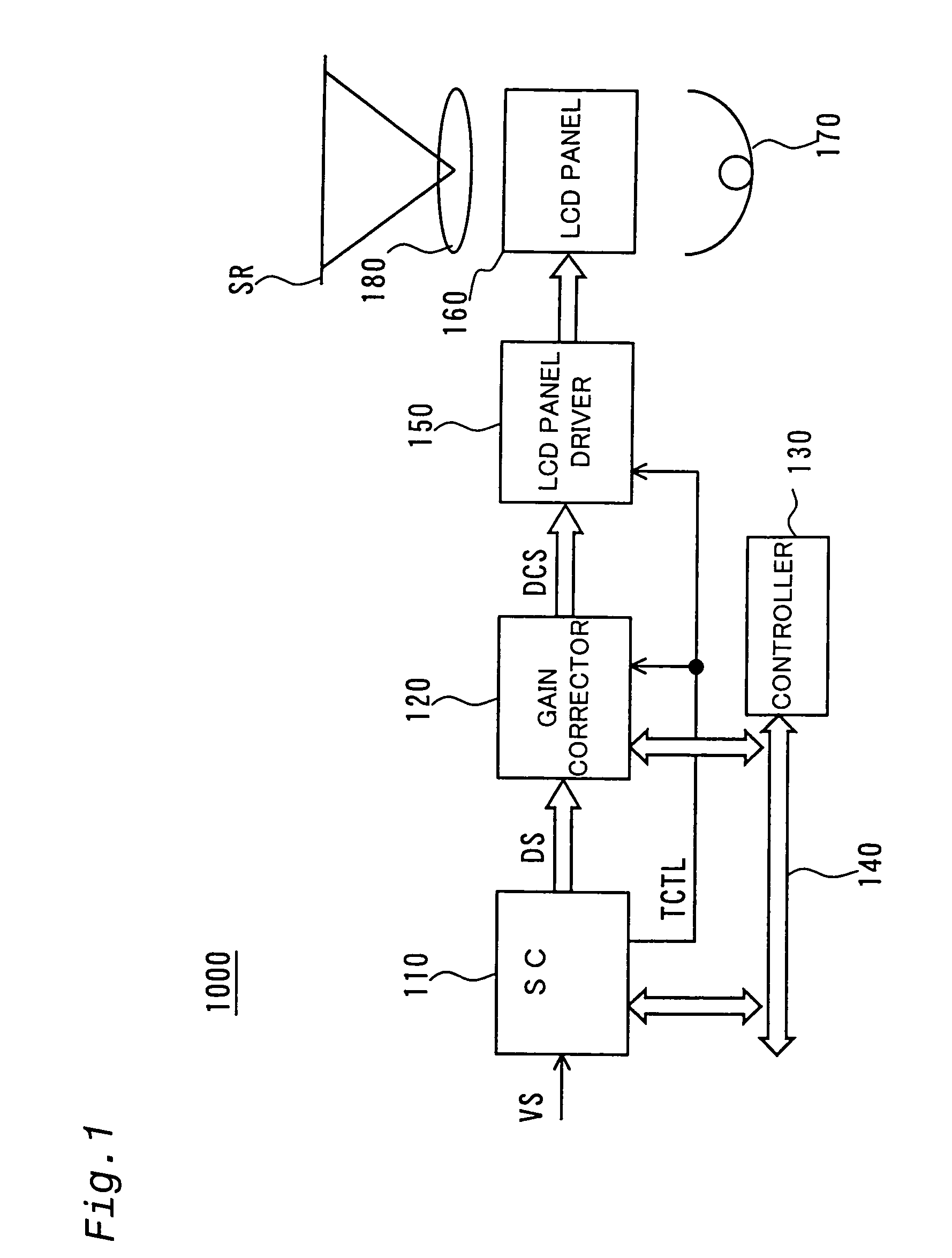
[0034]FIG. 1 is a block diagram schematically illustrating an image display 1000 that is a first embodiment of this invention. The image display 1000 comprises a scan converter (SC) 110, a gain corrector 120, a controller 130, a liquid crystal panel driver 150, liquid crystal panels 160, an illumination optical system 170 and a projection optical system 180. The image display 1000 is a projector which displays images by projecting red, green and yellow light exiting from the liquid crystal panels 160 at every pixel onto a projection screen SR through the projection optical system 180. The structures of the liquid crystal panel 160, illumination optical system 170 and projection optical system 180 are described in assignee's Japanese Patent Laid-Open Gazette No. 10-171045, the disclosure of which is incorporated herein by reference for all purposes.

[0035]The controller 130 is connected to the SC 110 and the gain corrector 120 through a bus 140. The controller 130 sets the processin...

second embodiment

B.

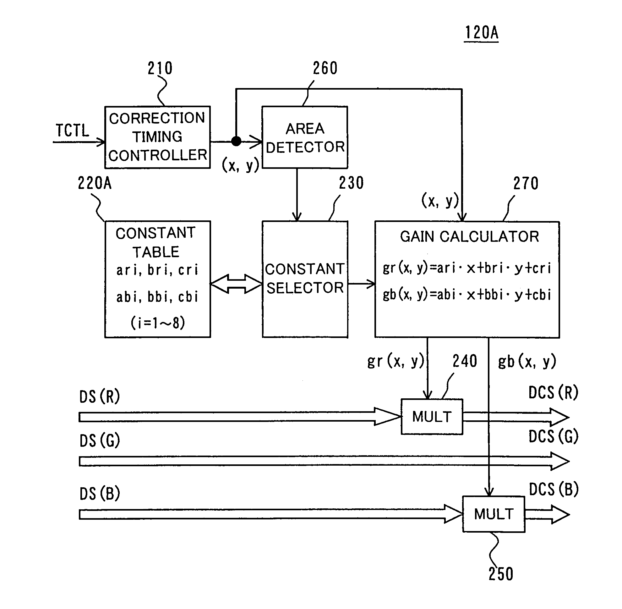
[0057]FIG. 4 is a block diagram schematically illustrating a gain corrector 120A of a second embodiment of this invention. An image display similar to that of the first embodiment can be configured by replacing the gain corrector 120 of the first embodiment with this gain corrector 120A.

[0058]The gain corrector 120A comprises a correction timing controller 210, a constant table 220A, a constant selector 230, a red multiplier 240, a blue multiplier 250, an area detector 260 and a gain calculator 270.

[0059]The area detector 260 detects a segment (hereinafter called an “area” or “plane”) that includes the pixel position (x, y) calculated by the correction timing controller 210. The meaning of “area” will be explained with reference to FIG. 5. Among multiple pixels arrayed in a matrix, designate those at the four corners as PA, PC, PG and PI, designate the center pixel as PE, designate the pixels at the left and right ends of the horizontal line passing through the center pixel PE as ...


PUM


Abstract

The image display apparatus comprises: an image processor for outputting image data including plural color component data; a gain corrector for correcting levels of the image data output by the image processor; and an image display device having a plurality of pixels from each of whose pixels light for forming an image exits in accordance with the corrected image data corrected by the gain corrector. The gain corrector corrects the level of at least one of the plural color component data applied to the pixels in accordance with the positions of the pixels such that, when image data representing an image of a prescribed uniform color are output from the image processor, difference in chromaticity of light exiting from the pixels is reduced among the pixels without making luminance of the light exiting from the pixels of the image display device the same at all pixels.

Description

BACKGROUND OF THE INVENTION[0001]1. Field of the Invention[0002]The present invention relates to an image display for displaying color images.[0003]2. Description of the Related Art[0004]Various types of displays have been developed for displaying color images, including the direct viewing and projection types. The direct viewing display uses a liquid crystal panel, plasma display panel (PDP), CRT or the like to display an image that the viewer views directly. The projection display is equipped with a projection lens, various optical systems and a display device such as a liquid crystal panel, digital micromirror device (DMD, trademark of Texas Instruments Inc.) or CRT. An image formed on the display device is projected onto a screen, for instance, for viewing.[0005]Ideally, the image displayed by a color display is uniform, i.e., totally free of unevenness. Actually, however, unevenness sometimes arises in the displayed image for reasons that will now be discussed.[0006]When a liqu...

Claims


Application Information

Patent Timeline
IPC IPC(8): G09G5/10G09G5/02G09G3/36G02F1/133G09G3/20H04N9/12H04N9/77
CPCG09G3/2003G09G5/02G09G2320/0285G09G2320/02H04N9/77
Inventor KOYAMA, FUMIO
Owner SEIKO EPSON CORP
Why Eureka
Try Eureka