Optical unit, exposure apparatus, and device manufacturing method

a technology of exposure apparatus and exposure unit, which is applied in the direction of photomechanical apparatus, instruments, printing, etc., can solve the problems of deteriorating image forming characteristics of projection optical system, reducing surface accuracy, and greatly changing the refractive index of the gas inside the barrel, so as to improve the yield of high integration microdevices and improve the productivity. , the effect of high precision

Inactive Publication Date: 2006-05-23
NIKON CORP
View PDF18 Cites 6 Cited by
  • Summary
  • Abstract
  • Description
  • Claims
  • Application Information

AI Technical Summary

Benefits of technology

[0015]In addition, the second object of the present invention is to provide an exposure apparatus capable of performing exposure with high precision for over a long period of time.
[0056]In addition, in a lithographic process, by performing exposure with the exposure apparatus in the present invention, exposure with high precision is possible for a long period of time, and the yield of high integration microdevices can be improved, thus leading to an improvement in its productivity. Accordingly, furthermore from another aspect of the present invention, there is provided a device manufacturing method using the exposure apparatus in the present invention.

Problems solved by technology

Therefore, when gases such as nitrogen or oxygen enter the barrel filled with helium gas from the periphery, the refractive index of the gas inside the barrel greatly changes, which greatly deteriorates image forming characteristics of the projection optical system.
So, it is not appropriate to strongly fasten and hold the lenses to increase the air-tightness, because when this happens the lenses deform greatly due to stress, which leads to a decrease in the surface accuracy.
When the reticle or the wafer is exchanged, however, a huge amount of helium gas is consumed (leaks outside), creating problems from the viewpoint of running cost of the exposure apparatus.

Method used


Image

  • Optical unit, exposure apparatus, and device manufacturing method
  • Optical unit, exposure apparatus, and device manufacturing method
  • Optical unit, exposure apparatus, and device manufacturing method

Examples


Embodiment Construction

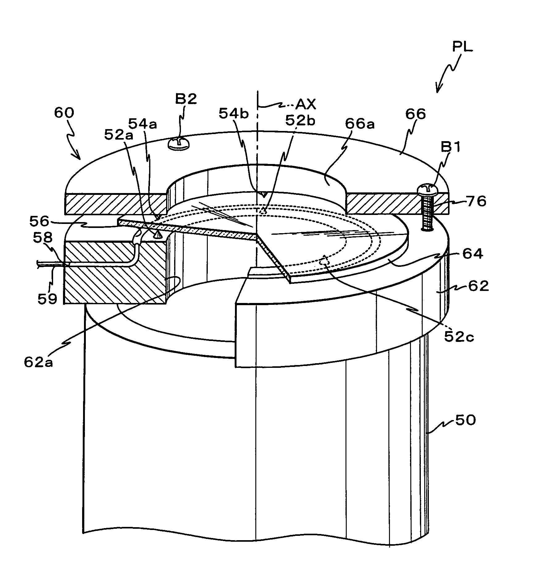
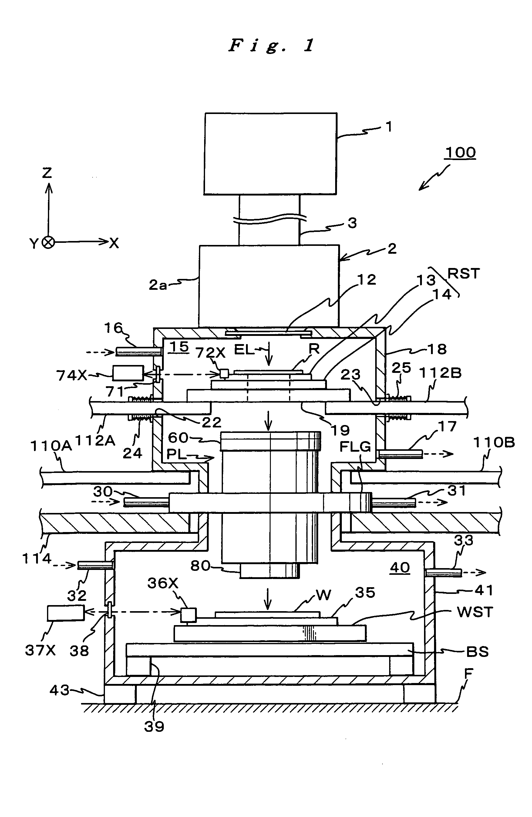
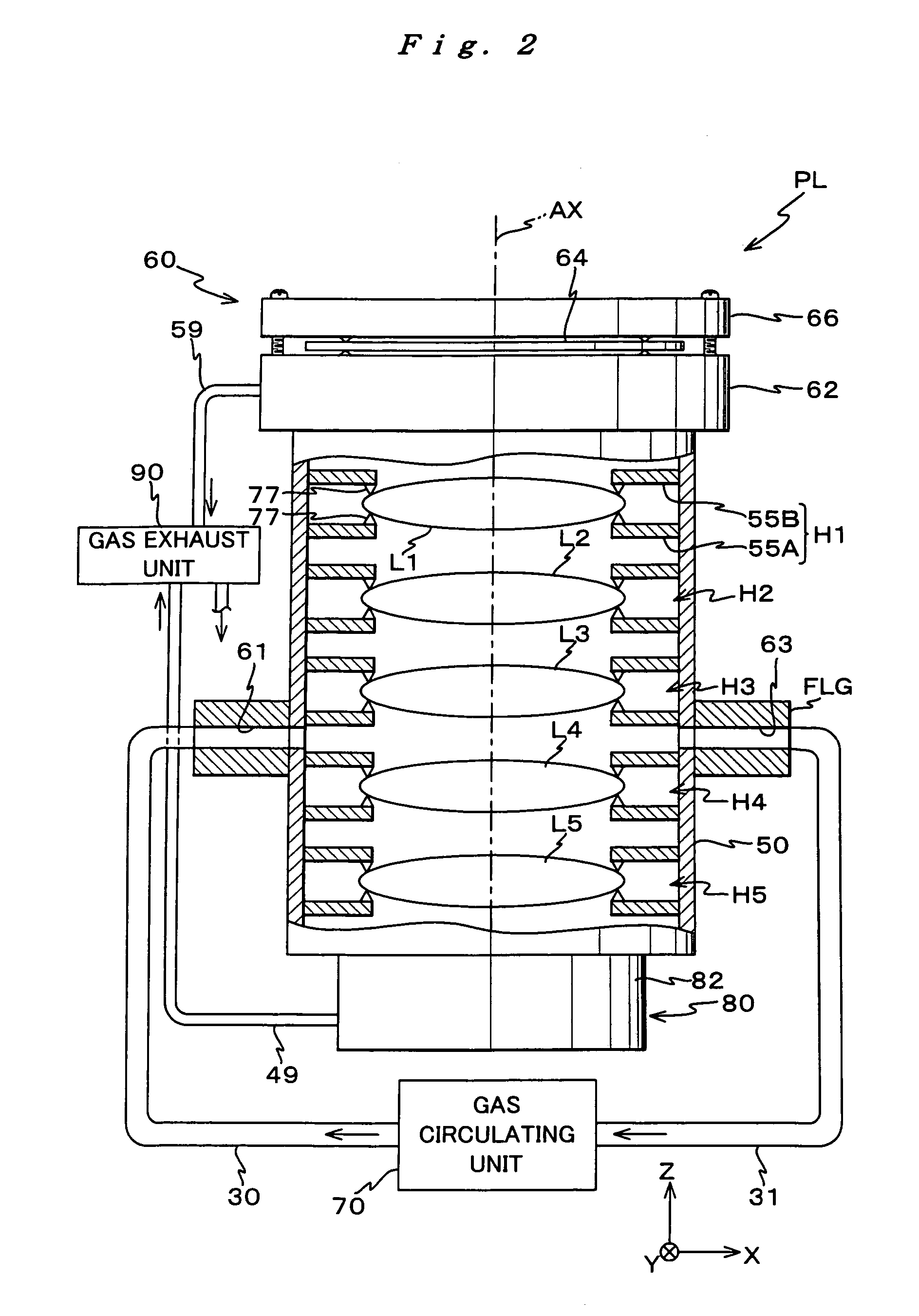
[0064]Referring to FIGS. 1 to 4, an embodiment of the present invention is described below. FIG. 1 shows an entire configuration of an exposure apparatus 100 related to the embodiment. Exposure apparatus 100 is a projection exposure apparatus based on a step-and-scan method, that is, a so-called scanning stepper. Exposure apparatus 100 illuminates an illumination light for exposure (hereinafter referred to as “exposure light”) EL serving as an energy beam that belongs to a vacuum ultraviolet region onto a reticle R serving as a mask, and transfers a pattern formed on the reticle R onto a wafer W serving as a substrate via a projection optical system PL serving as an optical unit.

[0065]Exposure apparatus 100 includes a light source 1 and an illumination unit 2. Exposure apparatus 100 also comprises: an illumination system for illuminating the reticle R with exposure light EL; a reticle stage RST for holding the reticle R; projection optical system PL for projecting exposure light EL ...


PUM

PropertyMeasurementUnit
wavelengthaaaaaaaaaa

Abstract

In a barrel of an optical unit a ring shaped support member is integrally arranged, and three projected portions are arranged on the upper surface of the support member. The projected portions support a lower surface of a parallel flat plate supported in direct contact. In this supported state, the parallel flat plate opposes a surface of the support member with a clearance of several μm in between. With this arrangement, the space in one side of the parallel flat plate is substantially isolated from the space in the other side. Accordingly, for example, even if gas environment in the space on one side of the parallel flat plate is different from the other side, gases can be effectively kept from mixing. In addition, since the parallel flat plate is supported at three coplanar points, deformation of the parallel flat plate can be suppressed due to the force supporting the parallel flat plate, thereby suppressing the index of refraction from varying.

Description

CROSS-REFERENCE TO RELATED APPLICATIONS[0001]This is a continuation of International Application PCT / JP01 / 09838, with an international filing date of Nov. 9, 2001, the entire content of which being hereby incorporated herein by reference, which was not published in English.BACKGROUND OF THE INVENTION[0002]1. Field of the Invention[0003]The present invention relates to optical units, exposure apparatus, and device manufacturing methods, and more particularly to an optical unit that has an optical path inside its barrel, an exposure apparatus that comprises the optical unit, and a device manufacturing method that uses the exposure apparatus for manufacturing electronic devices.[0004]2. Description of the Related Art[0005]Conventionally, various exposure apparatus have been used in a lithographic process for producing devices such as a semiconductor device and a liquid crystal display device. Among these apparatus, the ones mainly used in recent years are a reduction projection exposur...

Claims


Application Information

Patent Timeline
Patent Type & Authority Patents(United States)
IPC IPC(8): G03B27/52G02B15/14G02B7/02G03B27/42G03F7/20
CPCG03F7/70808G03F7/70825G03F7/70933G03F7/70883G03F7/70833H01L21/027
Inventor SHIRAISHI, NAOMASA
Owner NIKON CORP
Why Eureka
Try Eureka