Method and apparatus for patterning magnetic media by contact printing

Inactive Publication Date: 2006-05-23
SEAGATE TECH LLC
View PDF6 Cites 17 Cited by
  • Summary
  • Abstract
  • Description
  • Claims
  • Application Information

AI Technical Summary

Benefits of technology

[0026]An advantage of the present invention is an improved method of forming a magnetic transition pattern in a magnetic material by contact printing.
[0027]Another advantage of the present invention is an improved method of forming a servo pattern in a magnetic recording medium.
[0028]Yet another advantage of the present invention is an improved apparatus for forming a magnetic transition pattern in a magnetic material by contact printing.
[0029]Still another advantage of the present invention is an improved apparatus for forming a servo pattern in a magnetic recording medium.
[0030]Additional advantages and other f

Problems solved by technology

Because of the locational precision needed, writing of servo patterns requires expensive servo-pattern writing equipment and is a time consuming process.
However, the above-described method incurs several drawbacks associated with its implementation in an industrially viable manner.
Specifically, a “one-of-a-kind” master writer with a very high write field gradient is necessary for writing the requisite high intensity, master magnetic servo pattern onto the master disk, and a complicated means for rotating the aligned master servo-writer disk and “slave” workpiece magnetic disk is required, as is a complex system for controlling/regulating/rotating t

Method used


Image

  • Method and apparatus for patterning magnetic media by contact printing
  • Method and apparatus for patterning magnetic media by contact printing
  • Method and apparatus for patterning magnetic media by contact printing

Examples


Example

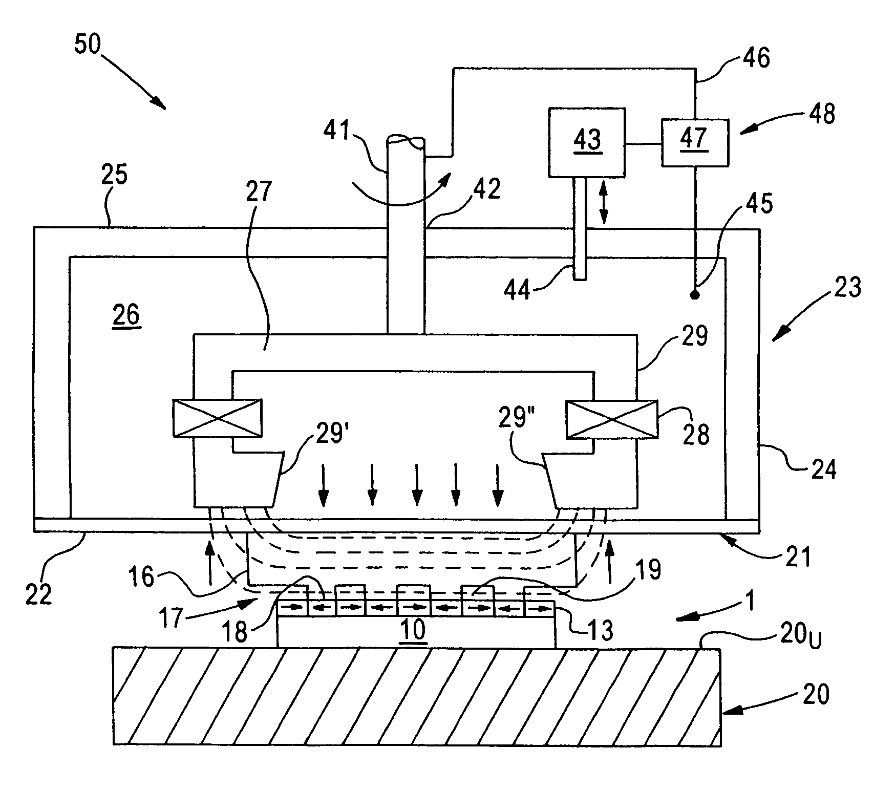
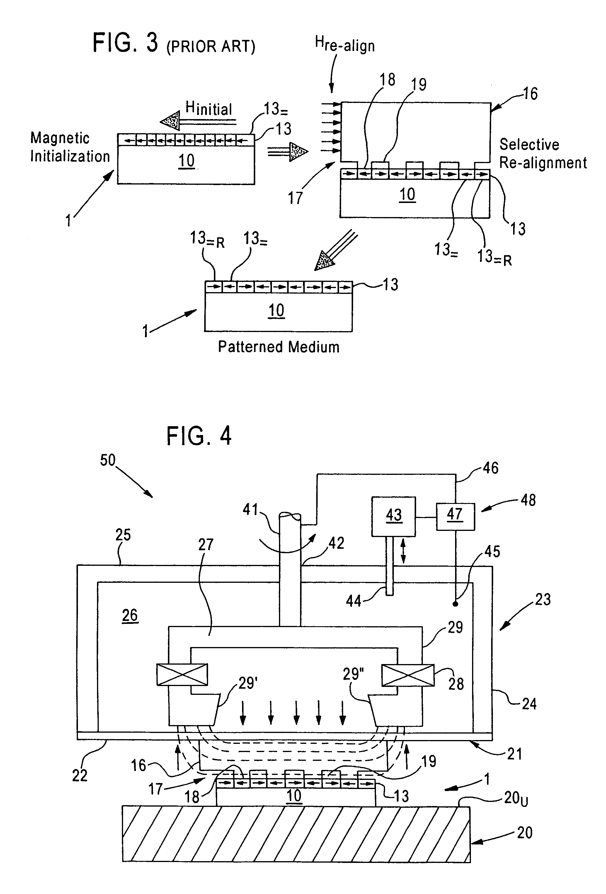
[0061]The present invention addresses and solves problems and difficulties attendant upon the use of stampers / imprinters in contact printing processing for creating magnetic transition patterns, for example servo patterns, in a magnetic material, e.g., a thin film of a magnetic material forming the active recording layer of a magnetic recording medium. The invention is an improvement over that disclosed in the aforementioned commonly assigned, co-pending U.S. patent application Ser. No. 10 / 082, 178, filed Feb. 26, 2002, and is based upon the discovery that a sufficient pressure must be applied to the stamper / imprinter when in contact with the magnetic material to be patterned in the presence of the magnetic re-alignment field in order to overcome magnetic attraction between the stamper / imprinter and the source of the magnetic re-alignment field, thereby maintaining contact between the imprinting surface of the stamper / imprinter and the magnetic material over the entire extent of mut...


PUM


Abstract

An apparatus for forming a magnetic transition pattern in a magnetic material by contact printing, comprising:
    • (a) a stamper having an imprinting surface comprising a plurality of projections and depressions arranged according to the magnetic transition pattern, the stamper being formed of at least one high saturation magnetization, high permeability magnetic material;
    • (b) means for supporting a workpiece such that a surface thereof comprised of the magnetic material is in contact with the imprinting surface;
    • (c) magnet means for applying a unidirectional re-alignment magnetic field to the stamper and workpiece to effect selective re-alignment of magnetic domains of portions of the magnetic material facing the depressions of the imprinting surface, such that the pattern of selectively re-aligned magnetic domains forms a pattern replicating the pattern of projections and depressions; and
    • (d) means for applying sufficient pressure to the stamper and workpiece to overcome magnetic attraction between the stamper and the magnet means to thereby maintain full contact therebetween.

Description

CROSS-REFERENCE TO PROVISIONAL APPLICATION[0001]This application claims priority from U.S. provisional patent application Ser. No. 60 / 392,785 filed Jun. 28, 2002, the entire disclosure of which is incorporated herein by reference.FIELD OF THE INVENTION[0002]The present invention relates to methods and devices for forming magnetic transition patterns in a layer or body of magnetic material. The invention has particular utility in the formation of servo patterns in the surfaces of magnetic recording layers of magnetic data / information storage and retrieval media, e.g., hard disks.BACKGROUND OF THE INVENTION[0003]Magnetic recording media are widely used in various applications, e.g., in hard disk form, particularly in the computer industry for storage and retrieval of large amounts of data / information in magnetizable form. Such media are conventionally fabricated in thin film form and are generally classified as “longitudinal” or “perpendicular”, depending upon the orientation (i.e., p...

Claims


Application Information

Patent Timeline
IPC IPC(8): G11B5/86
CPCB82Y10/00G11B5/865G11B5/743
Inventor WANG, LI-PING
Owner SEAGATE TECH LLC
Why Eureka
Try Eureka