X-ray micro-target source

a micro-target source and target body technology, applied in the direction of x-ray tube electrodes, x-ray tube target geometry, x-ray tube with very high current, etc., can solve the problems of unsuitable x-ray sub-micron radiation and large background x-ray radiation, and achieve the effect of reducing the charging up of the target body and being convenient to integrate with the target body

Inactive Publication Date: 2006-05-23
XRT
View PDF10 Cites 28 Cited by
  • Summary
  • Abstract
  • Description
  • Claims
  • Application Information

AI Technical Summary

Benefits of technology

[0012]It has been further appreciated, in accordance with the invention that the size and shape of the x-ray source as seen by the detector in microscopy is determined by the cross-section of the target at the position where the charged particle beam strikes the target taken parallel to the plane of the detector. While the dimensions of the target are limited in the plane parallel to the detector plane in order to define the x-ray source size, the target can be of arbitrary length in the direction normal to the detector plane. Lengthening the target in the direction normal to the detector plane will therefore increase the amount of target material available for x-ray production and so will increase the efficiency of x-ray production.
[0014]Preferably, the mount is a sufficient heat sink for heat generated in said target body by said beam of electrons as to substantially prevent softening or melting of said target while it is being irradiated by said beam of electrons.
[0025]The mount for the target body is preferably a good electrical conductor or semiconductor to minimise charging up of the target body, and possible consequent drift of the electron beam. The mount is preferably relatively massive heat sink which may conveniently be integral with the target body.

Problems solved by technology

Outstanding difficulties, however, are that the arrangement is very sensitive in two dimensions to e-beam / target alignment, and that background x-ray radiation can be quite substantial if the electron beam also strikes the target substrate.
Typically the x-ray source size for a bulk target is greater than 0.5 micron and so is unsuitable for x-ray sub-micron ultramicroscopy

Method used


Image

  • X-ray micro-target source
  • X-ray micro-target source
  • X-ray micro-target source

Examples


Embodiment Construction

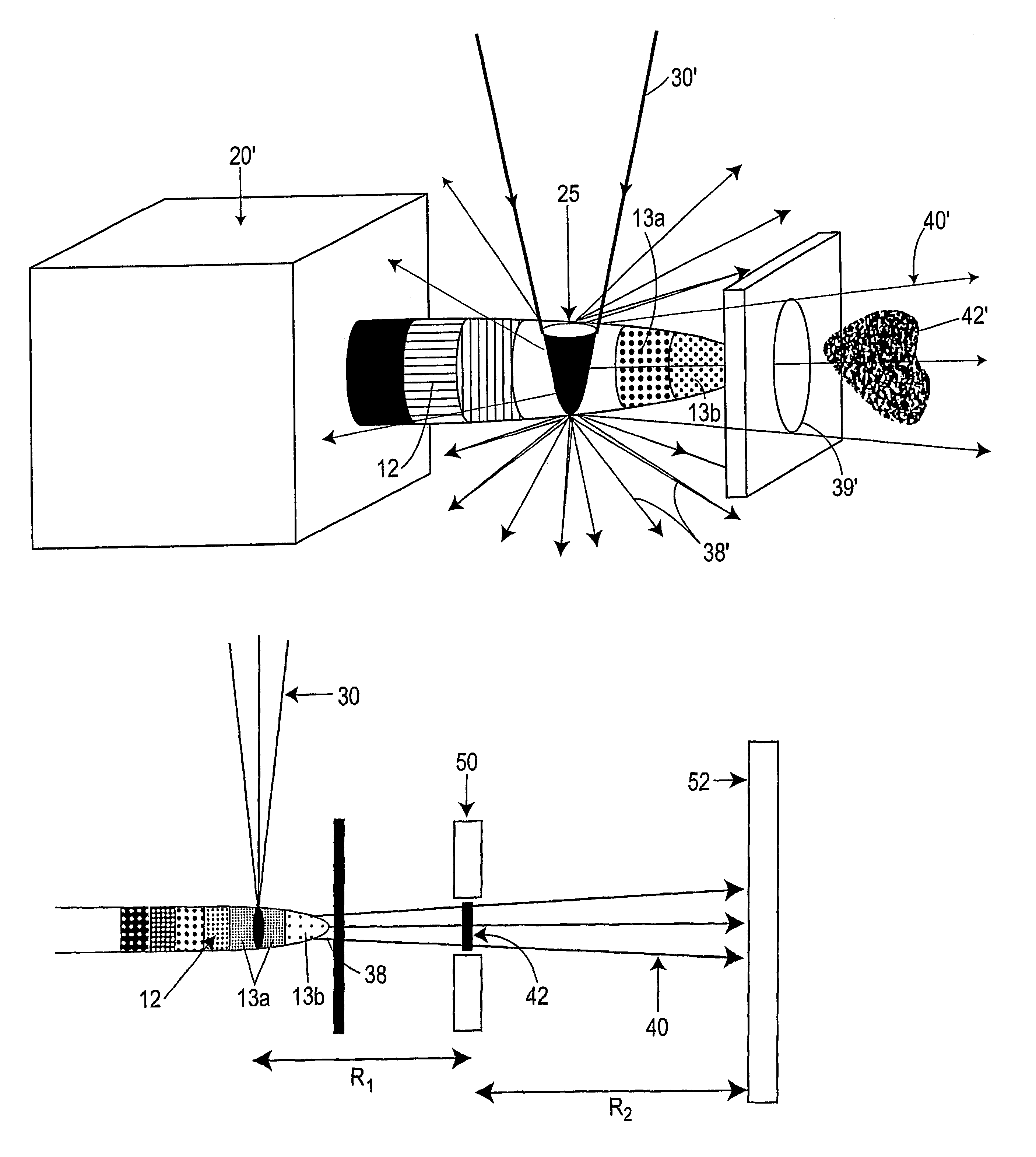
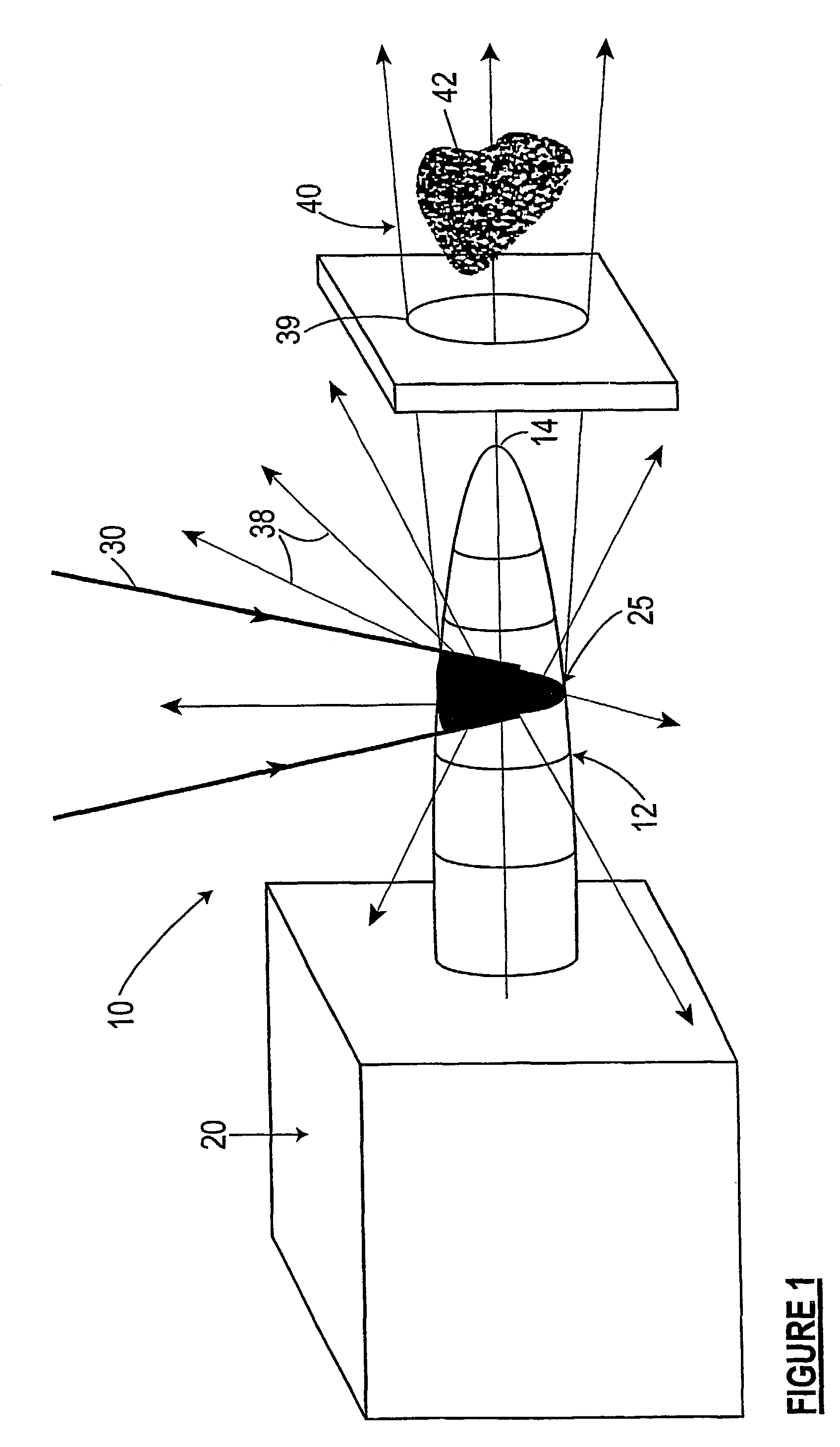
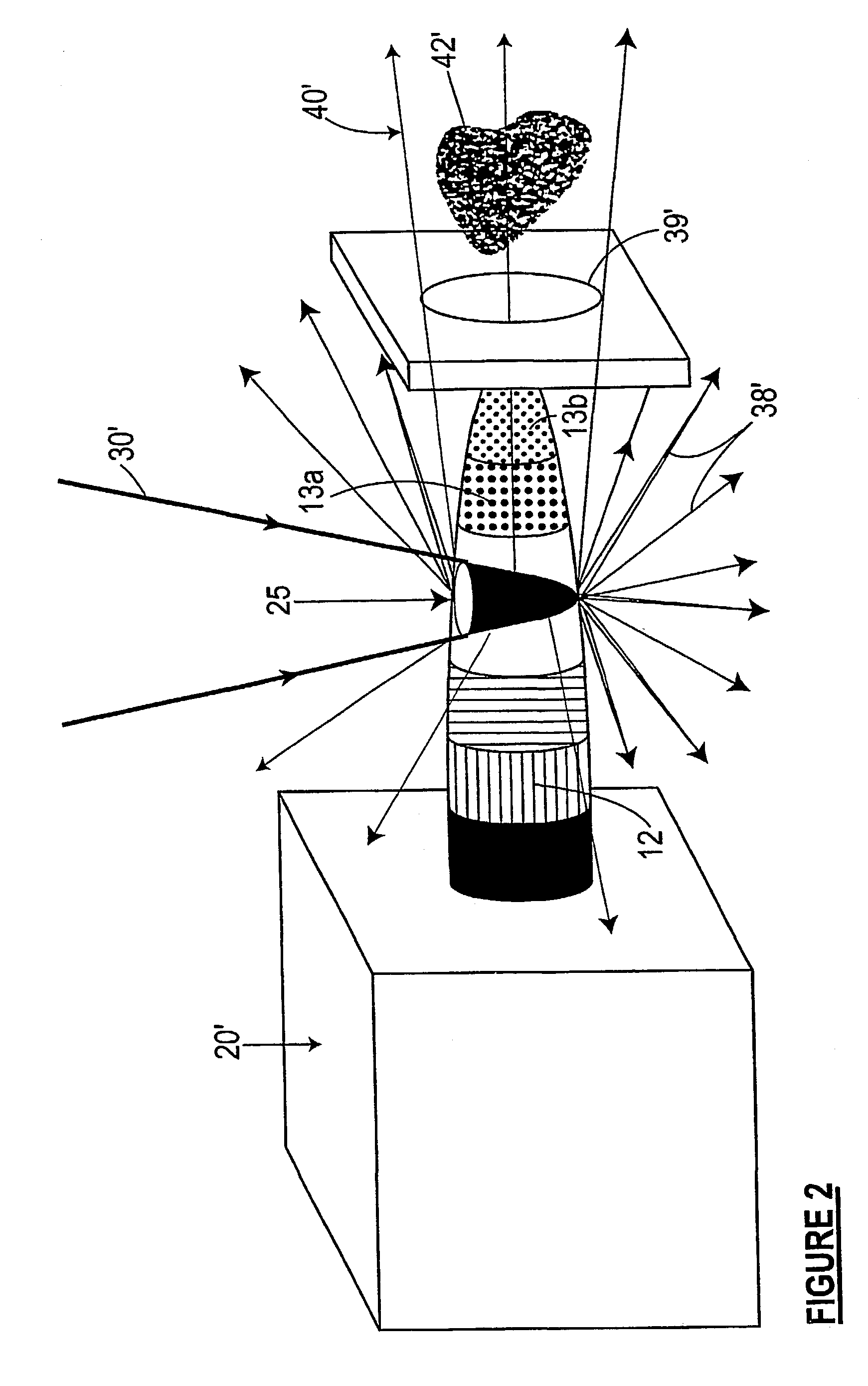
[0032]The arrangement illustrated diagrammatically in FIG. 1 comprises x-ray generation apparatus including an elongate target body 21 in the form of a solid needle or finger of a substance selected to generate a source of x-ray radiation 38 on being irradiated by a convergent beam of electrons 30 directed and focussed onto the target 12 from laterally of the target. Needle target 12 is an elongate cone of shallow taper angle and a relatively large radius smoothly curved or rounded tip 14. X-ray radiation 38 is emitted in all directions from a volume of interaction 25 of the electron beam 30 with the target body.

[0033]An aperture 39 serves as means defining a divergent beam or cone of illumination 40 of x-ray radiation emitted generally about tip 14 and directed laterally with respect to electron beam 30, eg. at 90° to beam 30, which may be utilised, for example, to irradiate a sample 42 that may be placed quite close to the tip 14 of the needle target.

[0034]Target 12 is illustrated...


PUM


Abstract

X-ray generation apparatus including an elongated target body and a mount from which the body projects to a tip remote from the mount. The target body includes a substance that, on being irradiated by a beam of electrons of suitable energy directed onto the target body from laterally of the elongate target body, generates a source of x-ray radiation from a volume of interaction of the electron beam with the target body. The mount provides a heat sink for the target body.

Description

RELATED APPLICATIONS[0001]This is a National Phase Application in the United States of America of International Application PCT / AU01 / 00750 filed 22 Jun. 2001, which claims priority from Australian Patent Application No. PQ 8312 filed 22 Jun. 2000.FIELD OF THE INVENTION[0002]This invention relates generally to x-ray micro-target sources, and is especially useful as a source excited by an electron beam of an electron microscope for use in x-ray ultramicroscopy. As such, the application of the invention extends generally to the high resolution x-ray imaging of features of very small objects, especially x-ray phase-contrast microscopic imaging, and to compositional mapping of such small objects at very high spatial resolution.BACKGROUND ART[0003]A known approach to microscopy utilising x-rays is projection x-ray microscopy, in which a focussed electron beam excites and thereby generates a spot x-ray source in a foil or other target. The object is placed in the divergent beam between the...

Claims


Application Information

Patent Timeline
Patent Type & Authority Patents(United States)
IPC IPC(8): H01J35/08G21K7/00H01J35/12H05G1/02H05H1/00H05H6/00
CPCH01J35/08H01J35/12G21K7/00H05H6/00G21K2207/005H01J2235/088H01J2235/1204H01J2235/086
Inventor WILKINS, STEPHEN WILLIAMMILLER, PETER ROBERT
Owner XRT
Why Eureka
Try Eureka