
Digitally controlled filter tuning for WLAN communication devices

a technology of digital control and filter tuning, applied in the field of filter tuning in, can solve the problems of high manufacturing and product cost, high power consumption of conventional wlan communication devices, and insufficient circuitry for implementing master-slave tuning technique, so as to reduce product and manufacturing cost, improve filter tuning accuracy, and reduce power consumption

Active Publication Date: 2006-05-23
MEDIATEK INC
View PDF3 Cites 14 Cited by
  • Summary
  • Abstract
  • Description
  • Claims
  • Application Information

AI Technical Summary

Benefits of technology

[0012]An improved filter tuning method and corresponding WLAN communication devices and integrated circuit chips are provided that may overcome the disadvantages of the conventional approaches. In particular, embodiments may allow for lowering the power consumption caused by the tuning circuitry. Other embodiments offer the advantage of reduced product and manufacturing costs. In further embodiments, the achievable communication data rate is increased. In still other embodiments, filter tuning accuracy is enhanced.

Problems solved by technology

However, substantial additional circuitry is required for implementing the master-slave tuning technique.
Therefore, conventional WLAN communication devices often suffer from the problem of increased power consumption.
In addition, those WLAN communication devices have the disadvantage of causing high manufacturing and product costs.
Yet, since filtering of the communication signal is interrupted while the filter cut-off frequency is being tuned, prior art WLAN communication devices applying the self-tuning technique often have difficulties in achieving efficient data rates.
Further, the filtering accuracy in those devices is decreased due to, e.g., cut-off frequency drift, during the time interval between the individual tuning interruptions.

Method used


Image

  • Digitally controlled filter tuning for WLAN communication devices
  • Digitally controlled filter tuning for WLAN communication devices
  • Digitally controlled filter tuning for WLAN communication devices

Examples


Embodiment Construction

[0020]The illustrative embodiments of the present invention will be described with reference to the figure drawings

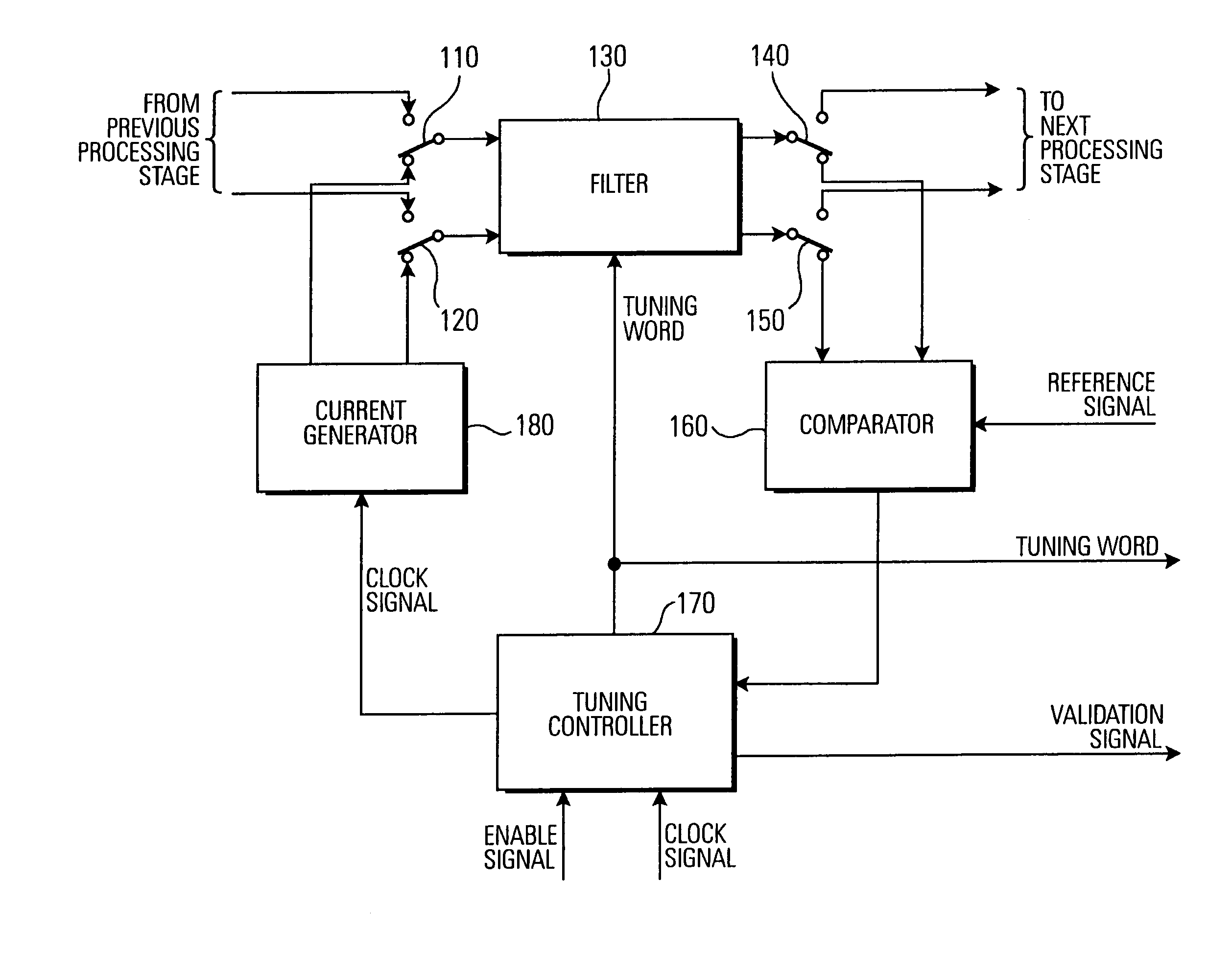
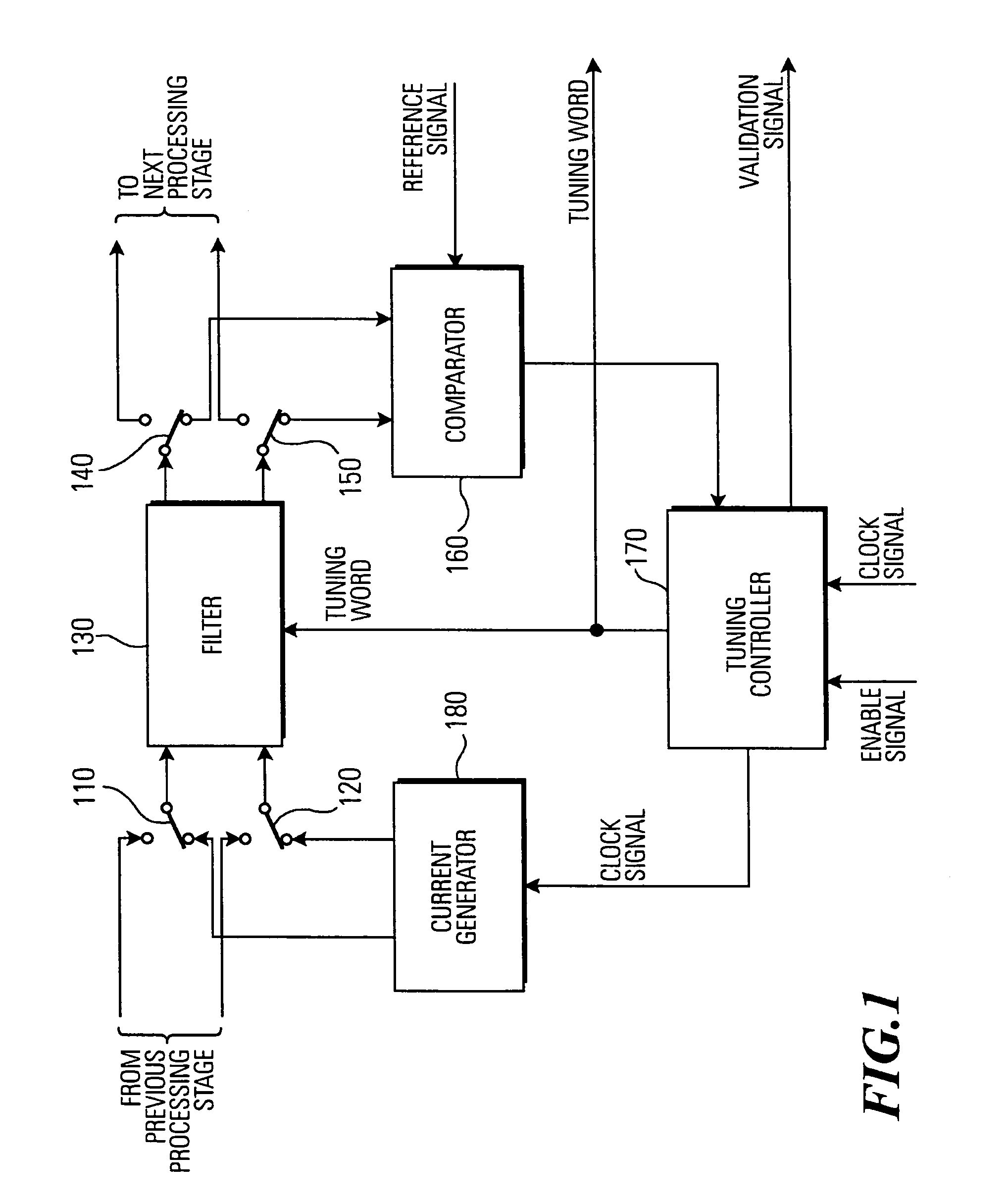
[0021]Referring now to the drawings and in particular to FIG. 1, components of a filter tuning implementation in a WLAN communication device according to an embodiment are shown. While the WLAN communication device is in a processing mode, a communication signal is passed from a previous processing stage acting on the communication signal within the WLAN communication device through a filter 130. The resulting filtered communication signal is forwarded from the filter 130 to a next processing stage within the WLAN communication device for further processing of the filtered communication signal. The previous processing stage and the next processing stage may comprise, e.g., mixers, amplifiers, A / D converters, etc.

[0022]According to the present embodiment, the WLAN communication device comprises switches 110, 120, 140, 150 for connecting the filter 130 either to the previ...


PUM


Abstract

A digitally controlled filter tuning method and corresponding WLAN (Wireless Local Area Network) communication devices and integrated circuit chips are provided. A WLAN communication signal is filtered by a tunable filter. A cut-off frequency of the tunable filter is tuned by a feedback loop. Tuning the cut-off frequency includes comparing by a comparator an output signal emitted by the tunable filter to a reference signal and emitting by the comparator a comparator signal indicative of the difference between the output signal and the reference signal. Further, tuning the cut off frequency comprises receiving the comparator signal by a tuning controller and setting by the tuning controller the cut-off frequency of the tunable filter based on the comparator signal by applying a digital tuning word to the tunable filter. The described filter tuning technique may reduce product and manufacturing costs while providing enhanced tuning accuracy.

Description

BACKGROUND OF THE INVENTION[0001]1. Field of the Invention[0002]The present invention relates to WLAN (Wireless Local Area Network) communication devices and corresponding methods and integrated circuit chips, and in particular to the filter tuning in such WLAN communication devices.[0003]2. Description of the Related Art[0004]A wireless local area network is a flexible data communication system implemented as an extension to, or as an alternative for, a wired LAN. Using radio frequency or infrared technology, WLAN systems transmit and receive data over the air, minimizing the need for wired connections. Thus, WLAN systems combine data connectivity with user mobility.[0005]Today, most WLAN systems use spread spectrum technology, a wideband radio frequency technique developed for use in reliable and secure communication systems. The spread spectrum technology is designed to trade off bandwidth efficiency for reliability, integrity and security. Two types of spread spectrum radio syst...

Claims


Application Information

Patent Timeline
Patent Type & Authority Patents(United States)
IPC IPC(8): H04B1/38H04B1/40H03H11/12H03L7/00H04L12/28H04L27/10
CPCH03H11/1291
Inventor BOLDT, JUERGENKLUGE, WOLFRAMBEYER, SASCHA
Owner MEDIATEK INC
Learn More