Digital group delay compensator

Active Publication Date: 2006-05-23
TELEDYNE LECROY
View PDF14 Cites 67 Cited by
  • Summary
  • Abstract
  • Description
  • Claims
  • Application Information

AI Technical Summary

Benefits of technology

[0031]3. Provides reliable compensation with feed

Problems solved by technology

Although the achievement of constant group delay, or linear phase is the basic goal of a phase com

Method used


Image

  • Digital group delay compensator
  • Digital group delay compensator
  • Digital group delay compensator

Examples


Embodiment Construction

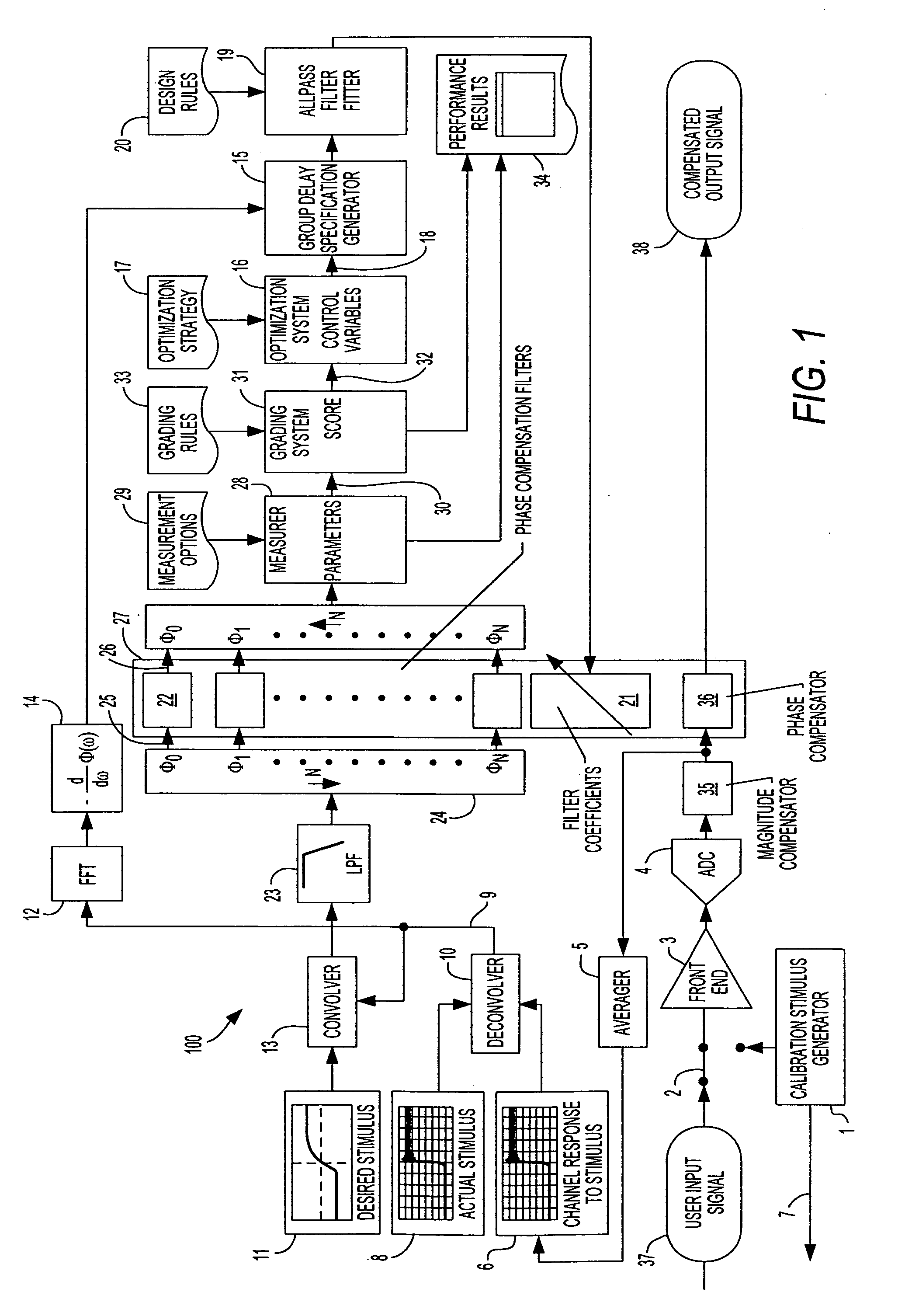
[0050]FIG. 1 shows a block diagram of a group delay compensator system 100 that accomplishes these objectives.

[0051]As is shown in FIG. 1, a calibration stimulus generator 1 is provided. When the system is calibrated, calibration stimulus generator 1 is switched into a front-end amplifier 3 via a switch 2. Under this configuration, the stimulus from calibration stimulus generator 1 is acquired via the analog channel consisting of front-end amplifier 3, an ADC 4, into an optional memory (not shown) and on through a magnitude compensator 35, and averager 5. The stimulus is acquired and averaged repeatedly to form a high-sample rate, low noise rendering of the stimulus. The result is retained as a channel response to the stimulus 6. Alternatively, external hardware, such as a probe connected to the input, could be connected to the external output of the calibration stimulus generator 7 such that any acquisitions would include the characteristics of the external hardware in the channel ...


PUM


Abstract

A digital group delay compensation system comprising a digital allpass filter that is utilized in an implementation phase; and a system that generates coefficients for the allpass filter used in the implementation phase such that the overall performance of a system is measured and optimized in a calibration phase.

Description

CROSS REFERENCE TO RELATED APPLICATIONS[0001]This application claims the benefit of U.S. Provisional Patent Application 60 / 416,705, filed Oct. 7, 2002, the entire contents of which are incorporated herein by reference.BACKGROUND OF THE INVENTION[0002]This invention pertains generally to sampled-data systems: systems containing at least a subsystem consisting of an analog input signal, some analog hardware, an analog-to-digital converter (ADC), a processing element such as a digital signal processor (DSP) and a processed output signal in digital form.[0003]This invention pertains specifically to such systems in which the phase characteristic is sub optimum. Phase is of particular interest because while magnitude response specifications can often be stated clearly, phase specifications often cannot. Magnitude response specifications are often made directly in the frequency domain. In other words, the specifications are a specific statement of desired magnitude response at particular f...

Claims


Application Information

Patent Timeline
IPC IPC(8): H04H1/04H04H20/77G01R13/02G01R27/28G06F19/00H03H17/08H04B3/46
CPCG01R13/0254H04B3/462G01R27/28H03H2222/02H03H17/08
Inventor PUPALAIKIS, PETER J.LAMARCHE, FRANCOIS
Owner TELEDYNE LECROY
Why Eureka
Try Eureka