Burner apparatus for burning fuel and air

a technology of burning fuel and apparatus, which is applied in the direction of lighting and heating apparatus, combustion types, machines/engines, etc., can solve the problems of affecting the combustion process, so as to reduce the amount of carbon monoxide produced, reduce the maximum pressure amplitude, and reduce the effect of air flow

Inactive Publication Date: 2006-05-30
SIEMENS AG
View PDF21 Cites 9 Cited by
  • Summary
  • Abstract
  • Description
  • Claims
  • Application Information

AI Technical Summary

Benefits of technology

[0015]To achieve the stabilisation effect in a burner having a premixing chamber no essential change of the method for injecting fuel is necessary, as only the flow of air is influenced to generate an enriched fuel / air mixture. The air blocking member is positioned upstream the premixing zone of the premixing chamber. It delays the portion of the flow of air and so produces a local pressure loss in the flow which causes a lower flow velocity to prevail behind the air blocking member than in the portions of the flow unaffected by the air blocking member. Beside locally and discrete reduction of air flow caused by the blocking member the air flow as well as the mixture of fuel in air is almost homogeneous at the outlet of the premixing chamber.
[0016]In a burner design which tends at certain operating conditions to develop combustion induced vibrations the use of an appropriate blocking member according to the invention would furthermore largely suppress the formation of combustion induced vibrations and also reduces the maximum pressure amplitude of those combustion induced vibrations which eventually still develop. The maximum amplitude may be reduced by a factor of four or more. In addition the use of an appropriate blocking member either in a burner design tending to develop combustion induced vibrations or a design free of those vibrations dramatically reduces the amount of carbon monoxide (CO) produced during the combustion process, in particular at higher air numbers. Experiments for example have shown that the emission of CO with 15% Oxygen (O2) can be reduced for air numbers between 3.0 and 3.4 to an amount of less than 200 ppm CO [15% O2]. For air numbers between 2.8 and 3.3 the emission of CO is reduced to less than 100 ppm CO [15% O2].
[0017]Number as well as location of the blocking elements and the location between blocking members, if more than one blocking member is used, are to be chosen according to the flow profile to be established. The arrangement of blocking members in the air inlet doesn't have to be symmetrical and may be performed in a way to obtain the best stabilisation effect. It is evident that the passive system of the invention for stabilising the premixing flame maybe easily used for refitting burner apparatus already in use.

Problems solved by technology

During the operation of a conventional premix burner, when the feeding of fuel to the burner is increased, a state is often reached in which the combustion becomes unstable and acoustic vibrations are caused in the plant into which it is fitted.
The combustion vibrations may be so great that they jeopardise the operation of the premix burner and the plant, of which the premix burner is an integral part.
This is achieved with the disadvantage of extracting air which is used to envelope the mixture from the actual combustion operation which markedly may increase the formation of nitrous oxides.
The secondary pilot burner provides additional fuel through a number of orifices at the outlet of the main burner, which leads to a non-uniform contribution of fluid at the outlet of the main burner.
To achieve this the installation of additional pipes for providing fluid a well as further mechanical features are necessary which makes the burner device more complicated and spacious.

Method used


Image

  • Burner apparatus for burning fuel and air
  • Burner apparatus for burning fuel and air
  • Burner apparatus for burning fuel and air

Examples


Embodiment Construction

[0038]In the figures of the drawing, components corresponding to one another of the respectively shown exemplary embodiments in each case have the same reference numeral.

[0039]The drawing is not to be considered as a representation of exemplary embodiments actually realised and is simplified in order to emphasise certain features. The information which can be gathered directly from the drawing can be supplemented for the practical construction within the limits of the knowledge and capability at the disposal of the persons skilled and active in the relevant art with due regard to the explanations preceding this information.

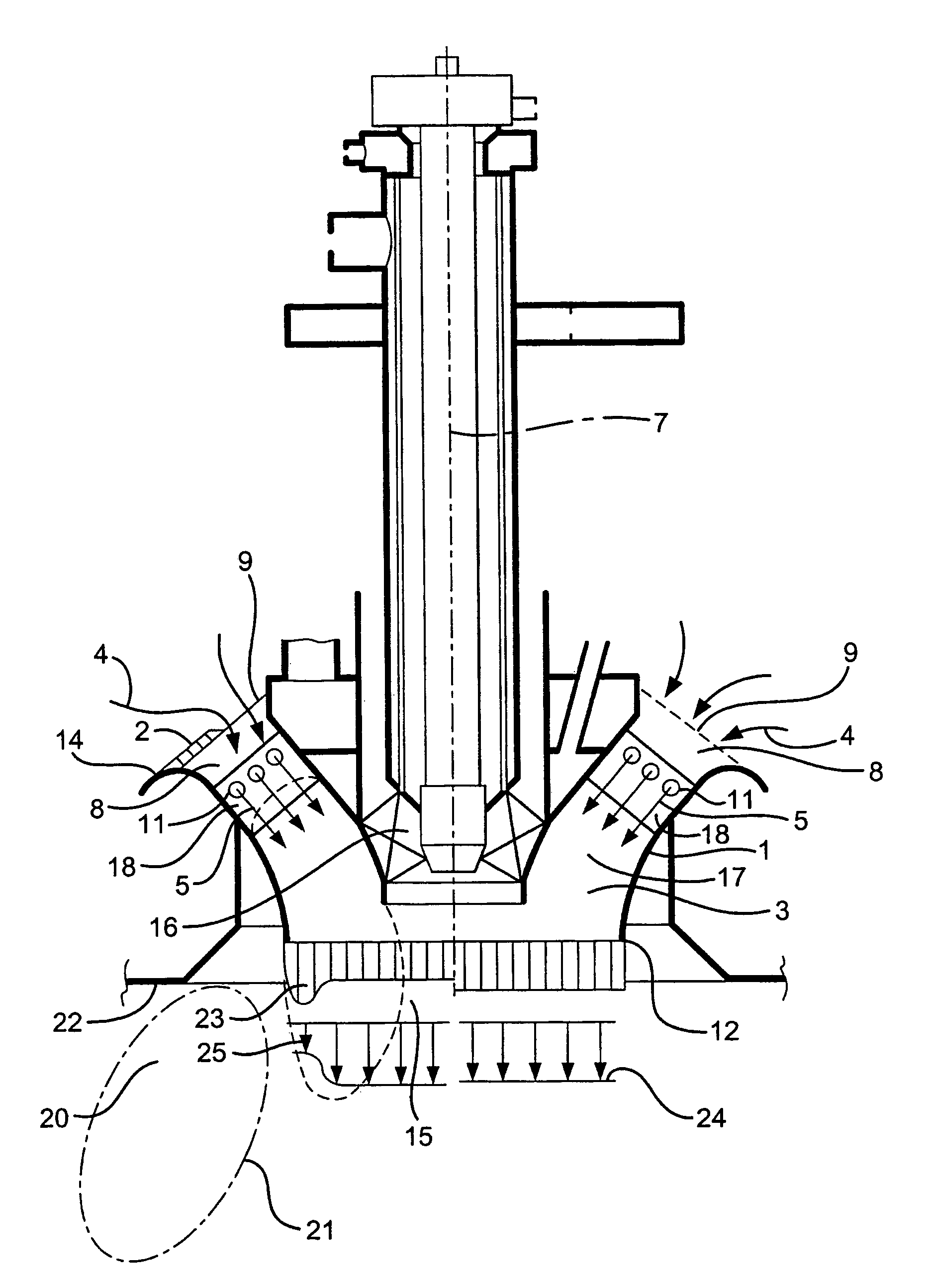
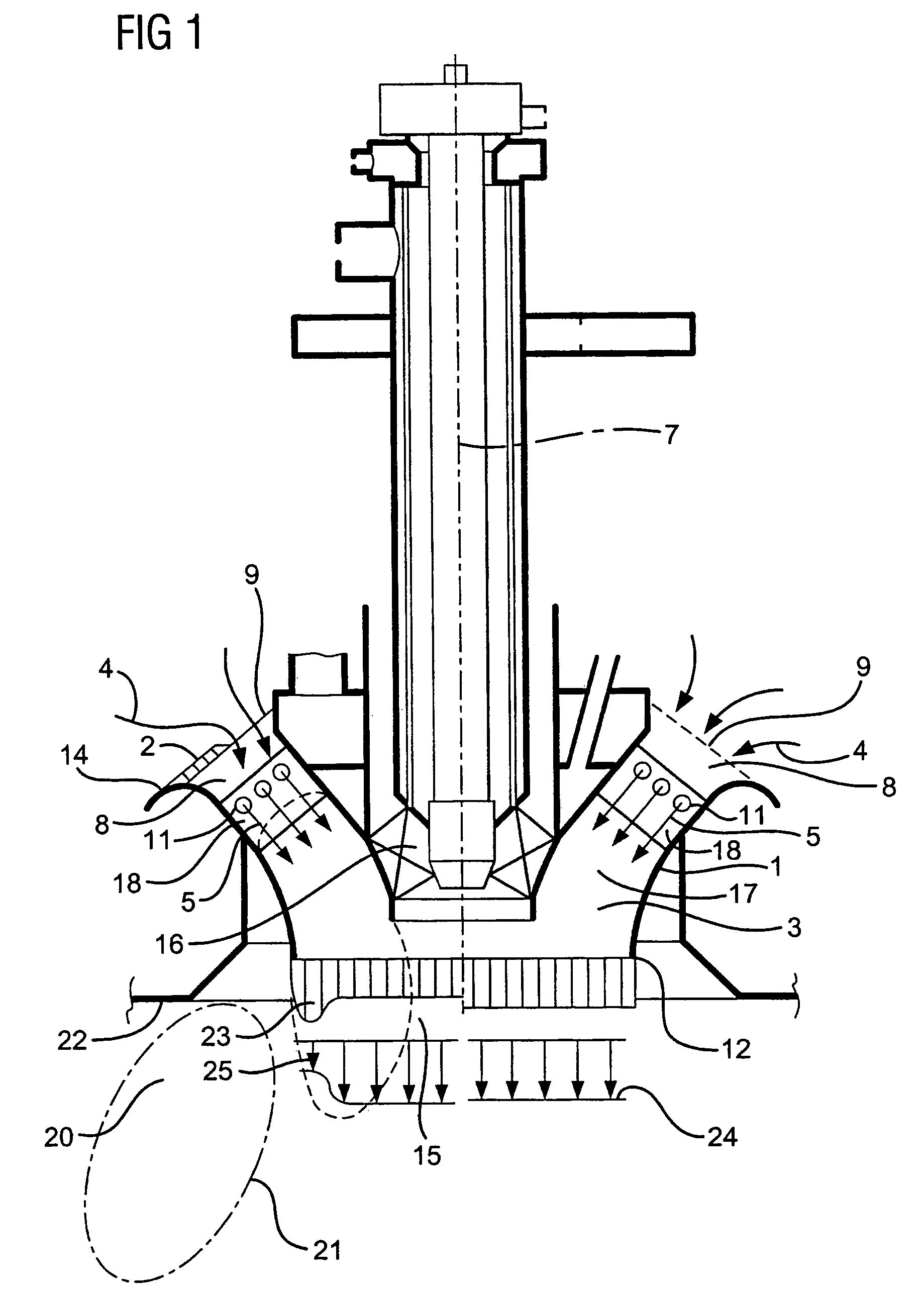
[0040]Referring now to the figures of the drawing in detail and first, particularly, to FIG. 1 thereof, there is shown an exemplary embodiment of the burner apparatus 1 according to the invention in a cross-sectional view along a main axis 7 of the apparatus 1.

[0041]The burner apparatus 1 extends along the main axis 7 and comprises a premixing chamber 3. The premi...


PUM


Abstract

The invention relates to a burner apparatus (1) for burning fuel (5) with air (4) to combustion gas, in particular within a combustion turbine, comprising a premixing chamber (3) for premixing fuel (5) and air (4) with. The premixing chamber (3) having an air inlet (8) for air (4) to enter said premixing chamber (3), a fuel inlet (11) for a gaseous or liquid fuel (5) to enter said premixing chamber (3), and an outlet (12) for a mixture of air (4) an fuel (5) wherein, the fuel inlet (11) being located between said air inlet (8) and said outlet (12). The burner apparatus (1) Further comprises at least one air blocking member (2) situated at the air inlet (8) for stabilising a burner premixing flame by locally blocking the flow of air (4) entering said premixing chamber (3) so that downstream said outlet (12) a locally inhomogeneous fuel concentration (23) results generating a locally hot stream of combustion gas being hotter than the average flame temperature.

Description

CROSS REFERENCE TO RELATED APPLICATIONS[0001]This application is a continuation of International Application No. PCT / EP02 / 05314, filed May 14, 2002 and claims the benefit thereof. The International Application claims the benefits of Great Britain application No. GB 0112147.4, filed May 18, 2001, both applications are incorporated by reference herein in their entirety.BACKGROUND OF THE INVENTION[0002]1. Field of the Invention[0003]The invention relates to a burner apparatus for burning a fuel in air and for stabilising a premixing flame, in particular a burner apparatus for a combustion turbine. The apparatus includes a premixing chamber in which fuel and air are premixed prior to burning the fuel.[0004]2. Description of Related Art[0005]Under the designation “premix burner” a burner device is known to persons skilled and active in the relevant art, with the feature that the fuel is burned only with a certain time interval after its intermixing with the air provided for the combustio...

Claims


Application Information

Patent Timeline
Patent Type & Authority Patents(United States)
IPC IPC(8): F23D14/62F23R3/12F02C7/232F23C9/00F23C99/00F23D14/02F23D14/74F23R3/18F23R3/28F23R3/34
CPCF23C9/006F23R3/18F23R3/286F23C2202/40F23D2209/20F23R2900/00014F23D2210/00
Inventor BLOMEYER, MALTE
Owner SIEMENS AG
Why Eureka
Try Eureka