Methods for making and using high explosive fills for very small volume applications

Inactive Publication Date: 2006-05-30
UNITED STATES OF AMERICA THE AS REPRESENTED BY THE SEC OF THE ARMY
View PDF4 Cites 10 Cited by
  • Summary
  • Abstract
  • Description
  • Claims
  • Application Information

AI Technical Summary

Benefits of technology

[0021]Advantageously, the method further comprises incorporating a polymeric binder into the slurry or paste to modify the viscosity of the mobile medium and improve the physical strength of the slurry or paste.
[0022]

Problems solved by technology

The aim is that this percentage should be as high as possible because cracks, porosity and the like reduce the power/performance of the secondary explosive and also, undesirably, increase the sensitivity of the explosive.
As a result, secondary explosive formulations are normally cast or pressed into final or near-final shape as described above because if such formulations were to be loaded as a slurry into a large volume munition, the drying time (for evaporation of the slurry medium) would be excessively long and the volatile medium would have to diffuse through dried material potentially causing defects in the fill such as porosity, voids, cracks, entrappe

Method used


Image

  • Methods for making and using high explosive fills for very small volume applications
  • Methods for making and using high explosive fills for very small volume applications
  • Methods for making and using high explosive fills for very small volume applications

Examples


example 1

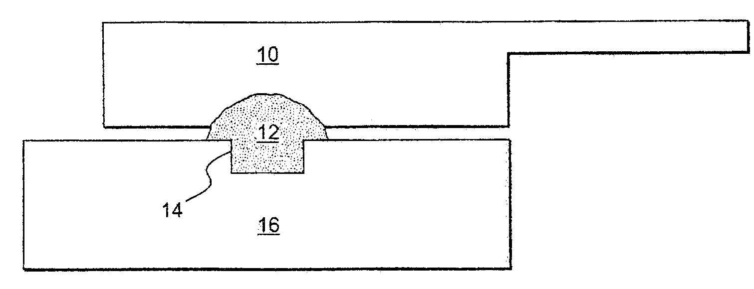
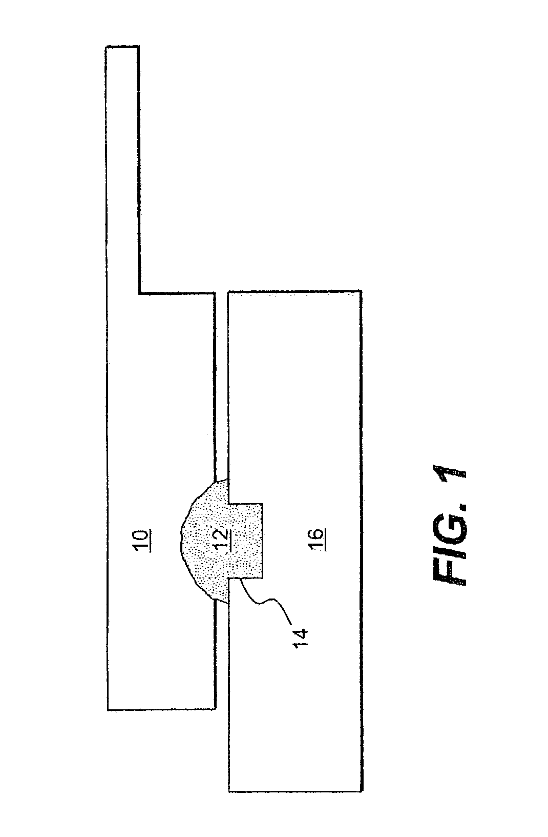
[0044]A small amount of a CL-20 slurry, prepared as described above, was taken up on a PTFE spatula and wiped over a loading hole in a fixture of an explosive device (as in FIG. 1). The mobile phase was allowed to dry. A loading hole in a second fixture was loaded with lead azide. Upon drying of the slurry mobile phase, an electrical resistance bridgewire was placed in direct contact with the lead azide and connected to the terminals of a battery. The CL-20 energetic material was successfully functioned.

example 2

[0045]A fixture was provided comprising a plate (made of PMMA or aluminum) having a hole drilled through the plate and a trough inscribed on the plate surface so as to be in communication with the hole. CL-20 was incorporated in a slurry with ethanol, and loaded into the hole in the plate with a small volume of the slurry placed in the trough. In addition, lead styphnate was placed in the trough in direct contact with the CL-20 and so as to partially fill the trough. Lead azide was then placed in the trough to fill the remaining trough volume. An electrical resistance bridgewire was placed in direct contact with the lead azide and the bridgewire was connected to the terminals of a battery. The device was successfully functioned and, in this regard, the primary explosives, lead styphnate and lead azide, set off the CL-20 fill material, which carried out a 90° corner turn and made a dent in a lead witness plate disposed in the end of the explosive train. In a closely related example, ...

example 3

[0046]A fixture plate made of PMMA or aluminum having a hole drilled through the plate thickness was provided and the hole was loaded as in Example 1. The device was successfully functioned using a low voltage electric bridgewire, with lead azide being used as the primary initiating explosive.


PUM


Abstract

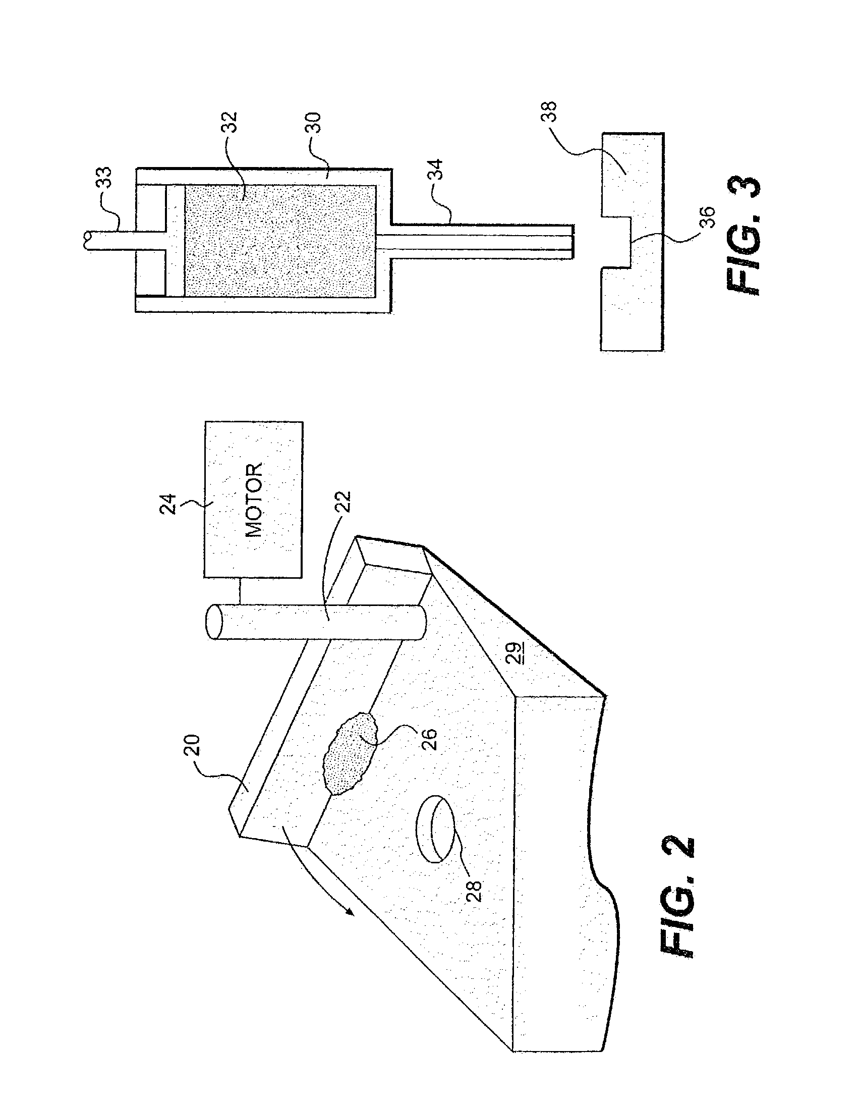
High explosives suitable for filling very small volume loading holes in micro-electric initiators for micro-electro-mechanical mechanisms, used as safe and arm devices, are prepared from slurries of crystalline energetic materials and applied using various methods. These methods include swipe loading, pressure loading and syringe loading. A volatile mobile phase may be added to the slurry so as to partially dissolve the energetic material so that, upon evaporation of the mobile phase, the energetic material precipitates and adheres to the loading hole.

Description

BACKGROUND OF INVENTION[0001]1. Field of the Invention[0002]The present invention relates to methods for preparing and using energetic fills containing crystalline high explosive materials.[0003]2. Related Art[0004]The basic standard methods for loading energetic or explosive materials into munitions are press-loading, and cast loading (whether using melt-cast or cast-cure techniques). With the relatively recent emergence of the production of smart weapon systems that are lighter and smaller and have greater lethality and survivability, the need exists for smaller, reliable Safe and Arm (S&A) devices for activating the explosive train of the explosive device. The challenges in producing Micro-Energetic Initiators (MEI) for Micro Electro-mechanical Mechanisms (MEMs) as safe and arm devices, involve the need to introduce the energetic materials into extremely small volumes and to have the energetic materials function properly after such introduction. MEIs for safe and arm devices will...

Claims


Application Information

Patent Timeline
IPC IPC(8): C06B45/10
CPCC06B21/0033F42B33/0207F42D1/10F42B33/0264F42B33/0242
Inventor STEC, III, DANIELCHENG, GARTUNGFUCHS, BRIAN E.GILLEN, GERARDMEHTA, NEHA
Owner UNITED STATES OF AMERICA THE AS REPRESENTED BY THE SEC OF THE ARMY
Why Eureka
Try Eureka