Solid-state self-emission display and its production method

Inactive Publication Date: 2006-05-30
JAPAN SCI & TECH CORP
View PDF7 Cites 0 Cited by
  • Summary
  • Abstract
  • Description
  • Claims
  • Application Information

AI Technical Summary

Benefits of technology

[0007]Taking into consideration the afore-mentioned problems, the object of the present invention is to provide a solid state light-emissive display apparatus which has much superior properties to existing display

Problems solved by technology

The display apparatuses using liquid crystals are lately in wide spread use, but these are not the best in such properties as energy-saving or brightness, since a liquid crystal display apparatus uses backlight in principle.
However, there are problems such that light emission efficiency is low and dielectric breakdown tends to occur, because considerably high electric field (106 V/cm or higher) is necessary to accelerate the electrons to such a high energy state (hot electron state) to emit EL light against the energy dispersion by phonon scattering.
T

Method used


Image

  • Solid-state self-emission display and its production method
  • Solid-state self-emission display and its production method
  • Solid-state self-emission display and its production method

Examples


Example

[0038]Hereinafter, a detailed explanation is given in respect to embodiment of the present invention, references being made to figures. In the drawing figures, it should be noted that the same reference characters are used to designate substantially the same or corresponding components.

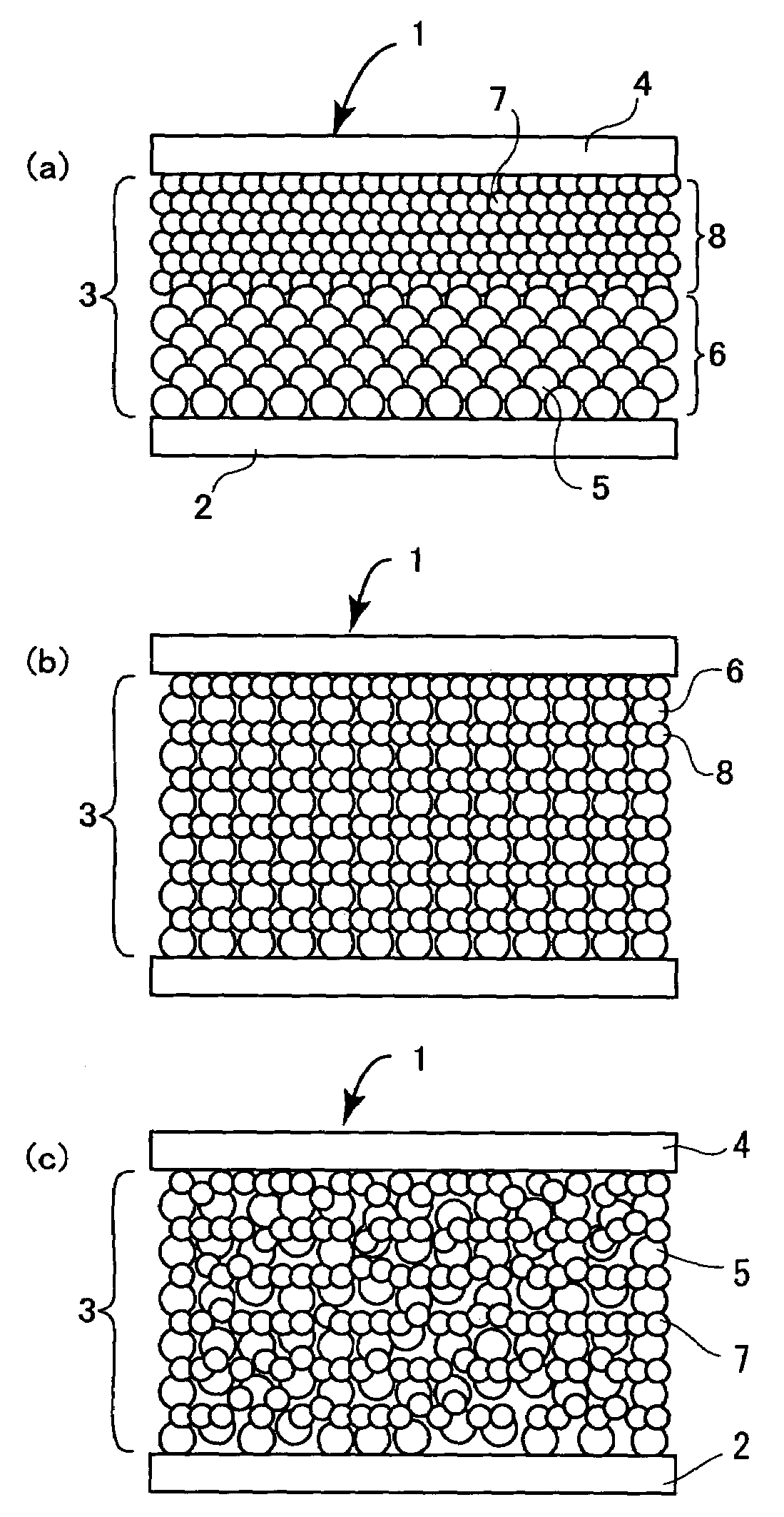
[0039]FIG. 1 is a diagrammatic cross-sectional view showing the makeup of a luminous part of a solid state light-emissive display apparatus of the present invention. FIG. 1(a) is a drawing showing the makeup of double layer lamination of a layer composed of crystal fine particles coated with insulator layer and a layer composed of fluorescent fine particles layer, FIG. 1(b) is a drawing showing the makeup of alternate lamination of each one layer composed of crystal fine particles coated with insulator layer and of fluorescent fine particles, and FIG. 1(c) is a drawing showing the makeup of lamination of a mixed layer composed of crystal fine particles coated with insulator layer and fluorescent fine ...


PUM


Abstract

The present invention provides a solid state light-emissive display apparatus of high brightness and efficiency, high reliability, and of thin type, and method of manufacturing the same at low cost.
Said apparatus has the luminous thin film made up by laminating or mixing crystal fine particle coated with insulator (5) of nm size and fluorescent fine particles (7) of nm size, and the lower electrode and the transparent upper electrode sandwiching said luminous thin film, wherein the electrons injected from said lower electrode are accelerated in the crystal fine particle coated with insulator layer (6) not being scattered by phonons to become high energy ballistic electrons, and form excitons (13) by colliding excitation of fluorescent fine particles. Since said fluorescent fine particles are of nm size, the exciton concentration is high, and luminescence intensity by extinction of excitons is also high.

Description

TECHNICAL FIELD[0001]The present invention relates to solid state light-emissive display apparatus utilizing a quantum size effect and method of manufacturing the same.BACKGROUND ART[0002]The display apparatuses using liquid crystals are lately in wide spread use, but these are not the best in such properties as energy-saving or brightness, since a liquid crystal display apparatus uses backlight in principle. For this reason, the research and development are widely proceeding for a solid state light-emissive display apparatus, aiming to realize high brightness, energy-saving, flat type, and high reliability rather more than liquid crystal.[0003]As an existing solid state light-emissive display apparatus, there is EL(Electro Luminescence) display apparatus. EL display apparatus is composed of pixels each of which has a semiconductor layer including light emission center atoms and insulator layers sandwiching said semiconductor layer. As a light emission center atom, such elements tha...

Claims


Application Information

Patent Timeline
IPC IPC(8): H01L33/00H05B33/14B82Y20/00G02F1/1335G09F9/00G09F9/30H01L27/32H05B33/10H05B33/12H05B33/22
CPCH05B33/10H05B33/22H05B33/145
Inventor ANDO, MASAHIKOSHIMADA, TOSHIKAZUSHIIKI, MASATOSHIODA, SHUNRIKOSHIDA, NOBUYOSHI
Owner JAPAN SCI & TECH CORP
Why Eureka
Try Eureka