
Linearization of an amplifier

a linearization and amplifier technology, applied in amplifiers, amplifier modifications to reduce noise influence, electrical devices, etc., can solve the problems of mixing between the different frequency components, affecting reducing the quality of the transmission, so as to reduce the distortion of intermodulation and achieve accurate reproduction, the effect of reducing the distortion

Inactive Publication Date: 2006-05-30
NOKIA SOLUTIONS & NETWORKS OY
View PDF10 Cites 38 Cited by
  • Summary
  • Abstract
  • Description
  • Claims
  • Application Information

AI Technical Summary

Benefits of technology

[0016]The embodiments of the invention may enable efficient use of the amplifying range of an amplifier while reducing the intermodulation the distortion present in the signal outputted from the amplifier. The embodiments may enable an amplifying circuit with linearization functionality that is less complex than that of F / F linearizers. The embodiments may enable use of linearizing circuitry operating at substantially lower frequencies than those used in F / F linearizers. The linearizing circuitry components may also be realized digitally. Therefore, once an embodiment has been designed, the embodiment may be reproduced accurately. The linearizing circuitry designed in accordance with the embodiments of the invention may also be substantially immune to temperature changes and the passage of time, as well as being small in size and power consumption.

Problems solved by technology

The amplification of the signals is required since the amplitude of a signal tends to be attenuated during the transmission of the signal between the signalling points, thereby decreasing the quality of the transmission.
Also, noise is added to the signal from other sources as well as from the transmitting and receiving and the possible intermediate apparatus itself.
Any amplifier introduces linear, or AM-PM (amplitude modulation-phase modulation) distortion, where amplitude variations in the input signal cause undesirable phase variations in the output signal, and intermodulation, or AM-AM distortion, causing mixing between the different frequency components present.
However, the third-, and to a lesser extent, the fifth-order distortion will dominate the nonlinearity of an amplifier in most cases.
The non-linearity of an amplifier is caused by the finite output power limitation and non-ideal transfer function of the amplifier.
However, this approach is not considered to be desirable in most applications as it fails to utilise the full range of available output voltage-swing and is therefore not power-efficient.
Feedforward linearizers are difficult to realize because all the components operate at radio frequency (RF), and the phase and amplitude tolerances of the two cancellation loops are very tight and susceptible to changes in temperature and ageing.
The feedforward linearizers are also temperamental, complex and inefficient to operate.
Due to the above reasons, feedforward linearizers are relatively expensive and may thus be unsuitable for some applications requiring linearization.
Predistortion linearizers operate to predistort the high-frequency carrier itself, and therefore suffer many of the drawbacks of F / F linearizers.
The current digital predistortion linearizers employ a complex structure, being difficult and expensive to realize.
Despite the complexity, even the digital predistortion linearizers have shown only a limited distortion improvement.

Method used


Image

  • Linearization of an amplifier
  • Linearization of an amplifier
  • Linearization of an amplifier

Examples


Embodiment Construction

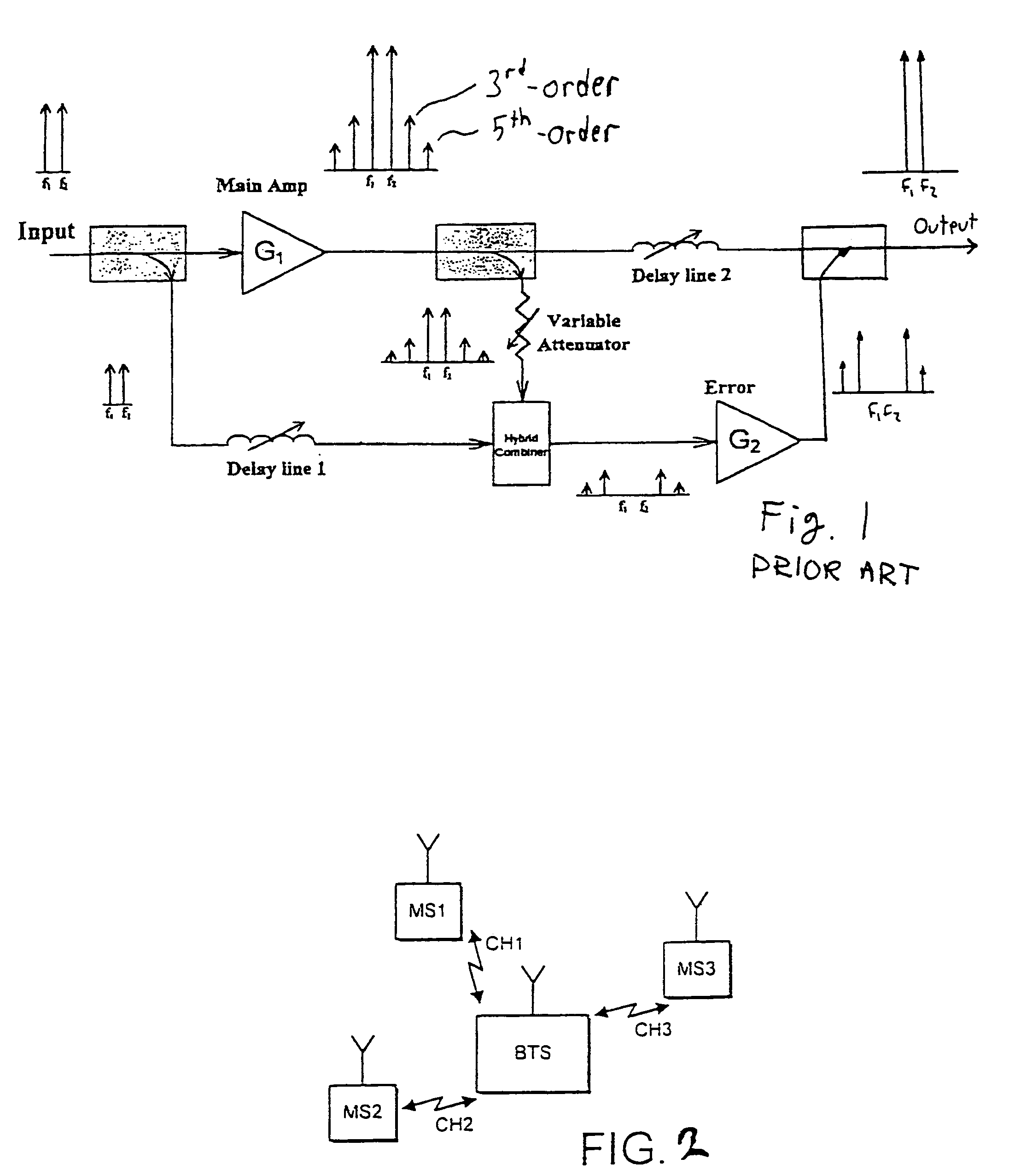
[0028]Reference will be first made to FIG. 2 illustrating a system in which the embodiments of the invention may be employed. The exemplifying system is a cellular mobile radio communication system allowing a plurality of mobile stations MS1, MS2, MS3 to communicate with a base (transceiver) station BTS in a common cell via respective channels CH1, CH2, CH3. Although not shown, the mobile stations may also move from one cell to another cell. The radio communication between a transmitting station and a receiving station may be implemented in any appropriate manner and may be based on any communication standard. Therefore the radio link as such will not be described in more detail herein. Examples of cellular communication systems include, without being limited to, standards such as AMPS (American Mobile Phone System), DAMPS (Digital AMPS), GSM (Global System for Mobile communications) or various GSM based systems (such as GPRS: General Packet Radio Service), CDMA (Code Division Multi...


PUM


Abstract

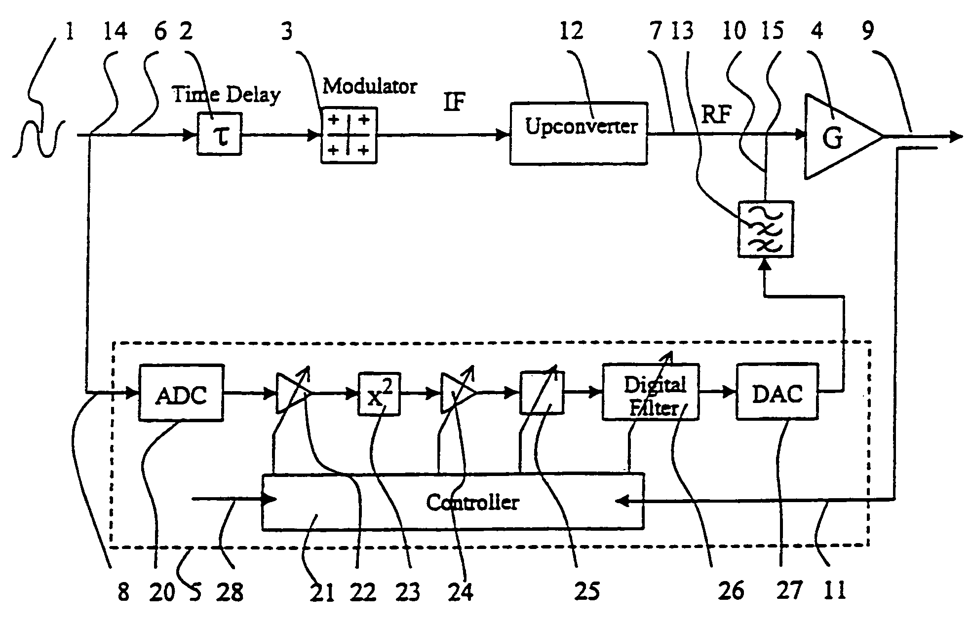
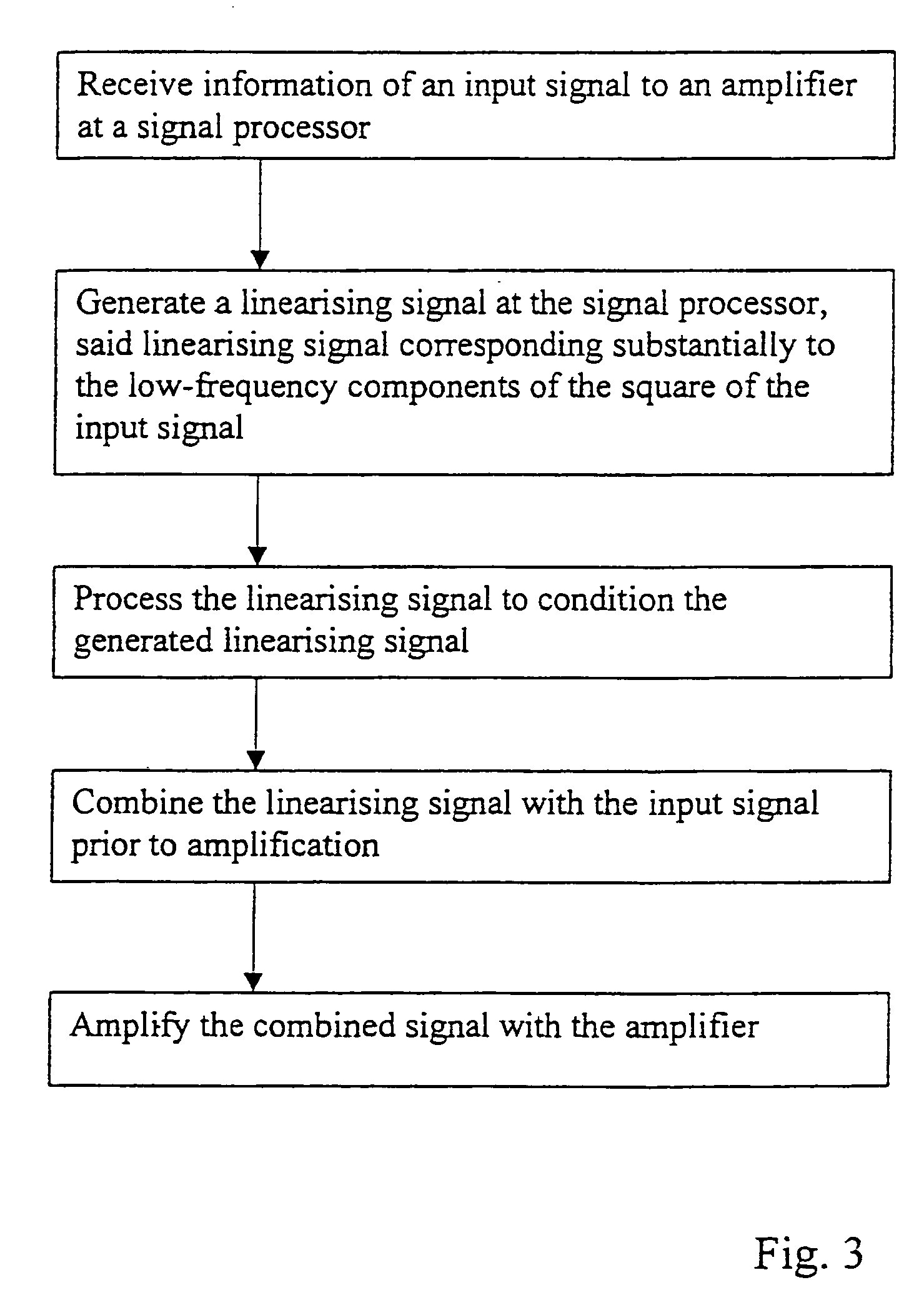
The present invention relates to a method of linearization an amplifier (4) and also to amplifier circuitry. The method comprises the steps of generating a linearization signal (10) that substantially corresponds to low-frequency components of the square of an input signal (7) to the amplifier (4), processing the linearization signal, combining (15) the linearization signal with the input signal to form a modified input signal, and amplifying the modified input signal by means of the amplifier (4).

Description

FIELD OF THE INVENTION[0001]The present invention relates to linearization of an amplifier and in particular, but not exclusively, to linearization of an amplifier for amplifying radio frequency signals.BACKGROUND OF THE INVENTION[0002]A communication system comprises signalling points or nodes, such as user terminals, different exchanges, routers, switches, links, stations and so on and an appropriate communication media between the signalling points. Signalling points may also be situated within an element of the communication system, wherein the communication may occur with the element. The communication media may comprise, for example, a wired interface, a radio interface or an optical interface. The communication may be carried by analogue or digital signals or a combination of these, such as digitally-modulated analogue signals.[0003]Amplification is required in various communication applications. For example radio frequency signals transmitted between signalling points in a r...

Claims


Application Information

Patent Timeline
IPC IPC(8): H03F1/26H03F1/32
CPCH03F1/3241
Inventor DARVISH-ZADEH, MAHMOUDKHANIFAR, AHMADJENKINS, WILLIAM
Owner NOKIA SOLUTIONS & NETWORKS OY
Learn More