
Patch antenna utilizing a polymer dielectric layer

a technology of dielectric layer and patch antenna, which is applied in the direction of resonant antennas, substantially flat resonant elements, transportation and packaging, etc., can solve the problems of unsatisfactory, markedly increased cost, and the dielectric constant of the dielectric layer directly affecting the dimensions of distributed circuit components, etc., to achieve reasonable size, improve the adhesion of the adhesive layer, and reduce the cost

Active Publication Date: 2006-05-30
WISTRON NEWEB
View PDF11 Cites 15 Cited by
  • Summary
  • Abstract
  • Description
  • Claims
  • Application Information

AI Technical Summary

Benefits of technology

The invention is a patch antenna that is small, durable, and reliable. It includes a metallic radiating element, a metallic ground plate, and a polymer plastic dielectric layer sandwiched between the radiating element and the ground plate. Adhesive layers adhere the radiating element and the ground plate to the dielectric layer. The antenna may also have priming layers to improve adhesion and a low noise amplifier may be integrated with it. The invention provides a cost-effective and reliable solution for small antennas.

Problems solved by technology

Besides the cost of the dielectric layer itself, the dielectric constant of the dielectric layer directly affects the dimensions of the distributed circuit components.
Air is obviously quite inexpensive, however air's low dielectric constant of 1.0 requires a relatively large-sized radiating element, which is not desirable in today's world of increasing miniaturization.
Near the opposite extreme of commonly used dielectric layers, ceramic's dielectric constant of 7.0–10.0 permits a relatively small-sized radiating element, with a downside of a markedly increased cost.
The use of a PCB as the dielectric layer permits a relatively small sized antenna, but is quite expensive.
Foam is quite inexpensive, but requires a much larger antenna due to its low dielectric constant.
Additionally, extreme changes in temperature make some materials unacceptable because temperature changes may break or alter bonding between the relative components or damage the assembled antenna.
Thus, manufacture, assembly, and reliability considerations frequently far outweigh any potential saving achieved by the choice of an inexpensive material having a relatively high dielectric constant.

Method used


Image

  • Patch antenna utilizing a polymer dielectric layer
  • Patch antenna utilizing a polymer dielectric layer
  • Patch antenna utilizing a polymer dielectric layer

Examples


Embodiment Construction

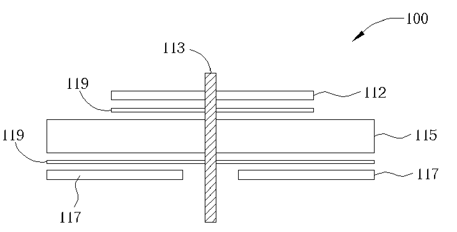
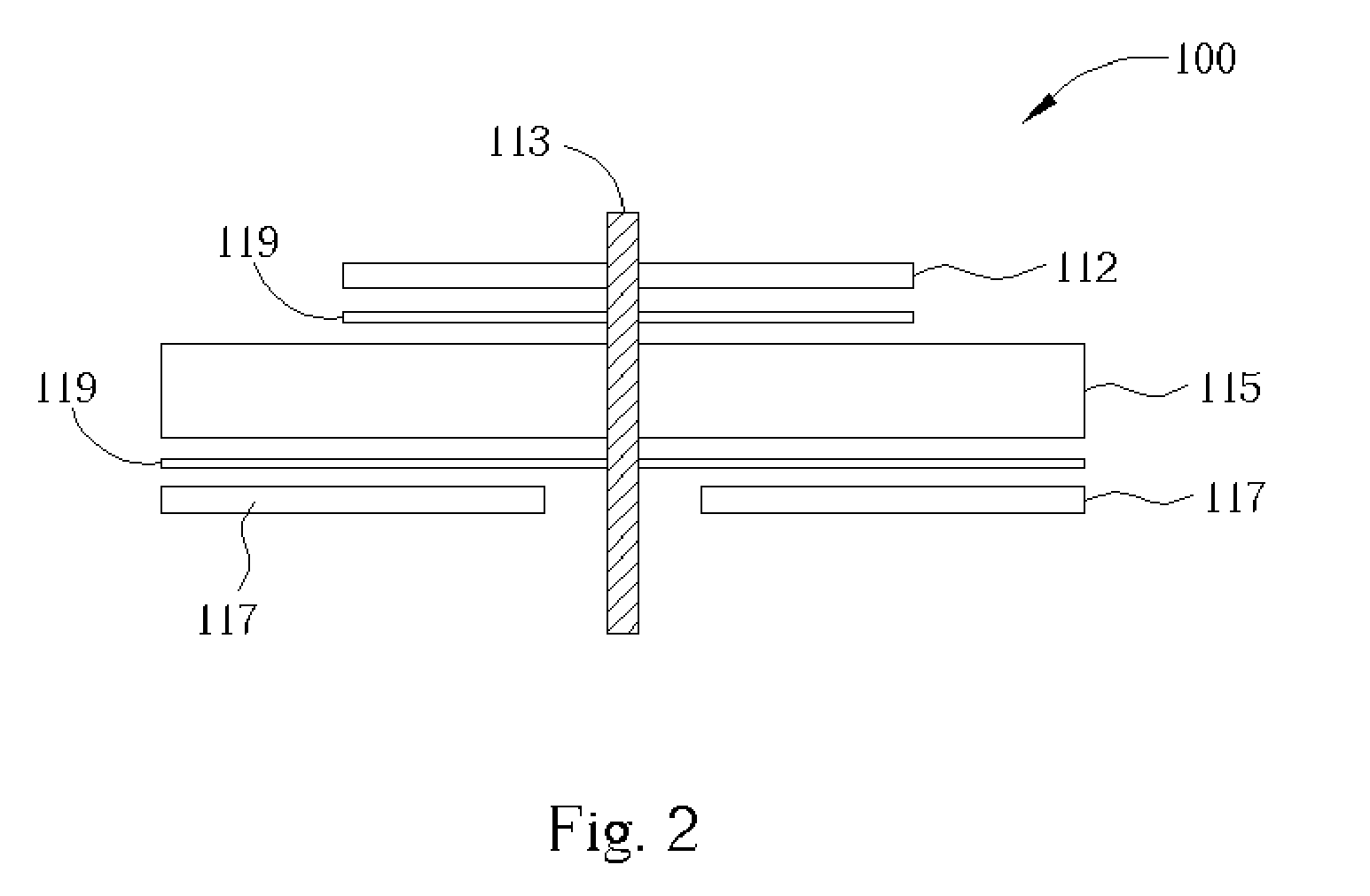
[0020]A patch antenna 100 according to the present invention comprises a radiating element 112, a ground plate 117, and a dielectric layer 115 sandwiched between the radiating element 112 and the ground plate 117 as shown in FIGS. 2–4.

[0021]The radiating element 112 preferably comprises a flat metallic plate, sheet, or layer somewhat rectangular in shape. As is known in the art, it is possible to improve gain by altering the shape of the radiating element 112 and / or other elements of the antenna 100 and as such, the scope of the present invention is not intended to be limited to any specific shape of any of the antenna's components.

[0022]The ground plate 117 also preferably comprises a somewhat rectangular, flat metallic plate, sheet, or layer and is located so that planes formed by the radiating element 112 and the ground plate 117 are approximately parallel and overlapping as shown in FIGS. 2–4. The ground plate 117 may be attached to a printed circuit board or other substrate all...


PUM

PropertyMeasurementUnit
dielectric constantaaaaaaaaaa
dielectricaaaaaaaaaa
polymericaaaaaaaaaa

Abstract

A patch antenna includes a metallic ground plate, a metallic radiating element, and a polymer plastic dielectric layer sandwiched between the radiating element and the ground plate. Top and bottom surfaces of the dielectric layer are primed with polymeric surfactants to provide better adhesive characteristics at low temperatures. The radiating element is fixed to the dielectric layer by compressing an adhesive layer applied to the radiating element between the radiating element and the priming layer applied to the top surface of the dielectric layer. The ground plate is fixed to the dielectric layer by compressing another adhesive layer applied to the ground plate between the ground plate and the priming layer applied to the bottom surface of the dielectric layer. A low noise amplifier may be integrated with the antenna by sharing the common ground plate and connecting the amplifier's signal trace to the radiating element via a conductor pin.

Description

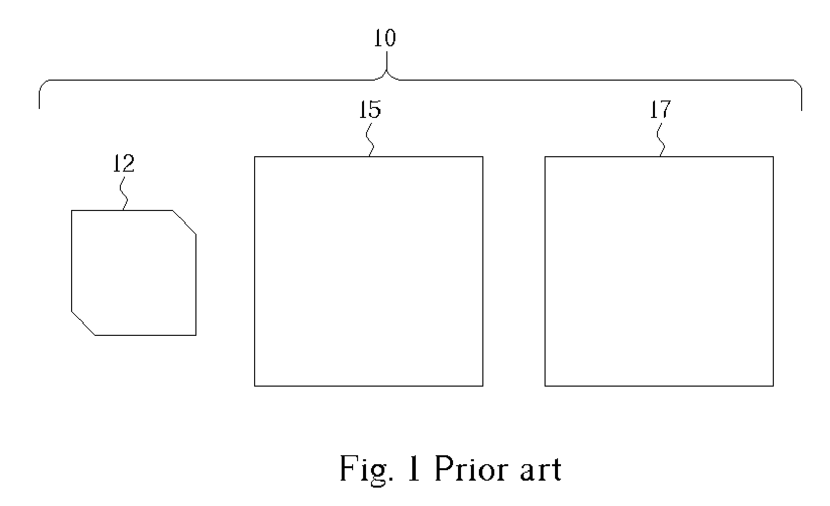
BACKGROUND OF INVENTION[0001]1. Field of the Invention[0002]This invention relates generally to antennas, and more specifically to the structure and assembly of a patch antenna utilizing a polymer plastic dielectric layer providing a reasonable sized antenna at a substantially reduced cost.[0003]2. Description of the Prior Art[0004]A conventional patch antenna in its simplest form is made of a rectangular conductive radiating element overlapping and approximately parallel with a conductive ground plate. A dielectric layer, or element, separates the radiating element from the ground plate. A basic structure of a typical patch antenna is shown in FIG. 1. The patch antenna 10 is assembled with the dielectric layer 15 sandwiched between the radiating element 12 and the ground plate 17.[0005]As is well known in the art, many of the properties of a patch antenna, specifically including size and cost, depend to a great degree upon the composition of the dielectric layer. Besides the cost o...

Claims


Application Information

Patent Timeline
Patent Type & Authority Patents(United States)
IPC IPC(8): H01Q1/38
CPCH01Q1/38H01Q9/0407Y10T428/24917
Inventor HSU, CHIEH-SHENGHUANG, CHANG-HSIUJAN, CHENG-GENG
Owner WISTRON NEWEB
Learn More