Method of calibration of magnification of microscopes having different operational principles for bringing them into a single, absolute scale

a technology of optical measuring microscope and magnification, which is applied in the direction of optical elements, instruments, optical radiation measurement, etc., can solve the problems of not being able to calibrate optical measuring microscopes in such a wide range of sizes, difficult to solve problems, and reference samples are completely unsuitable for calibration

Inactive Publication Date: 2006-05-30
GEN PHOSPHORIX
View PDF4 Cites 6 Cited by
  • Summary
  • Abstract
  • Description
  • Claims
  • Application Information

AI Technical Summary

Benefits of technology

[0008]When the method is performed in accordance with the present invention, it eliminates the disadvantages of the prior art and provides for the highly advantageous results which will be explained in detail herein below.

Problems solved by technology

There is no microscope which is capable to measure objects in such a broad range of sizes.
This problem is very difficult to solve since there is no universal calibrating standard which would be suitable for calibration of optical measuring microscopes, scanning electron measuring microscopes and probe microscopes.
This reference sample is however completely unsuitable for calibration of optical measuring microscopes and scanning electron measuring microscopes, since the resolution of the microscopes of this types is lower than required for visualization of the atom pattern, so that this pattern is not shown on the images of the microscopes of these two types and can not serve as a common standard.
Known attempts to use as a universal reference sample so-called “hand-made” objects have not been successful.
The obstacle in this approach is that the diffraction grating to be used can never be completely uniform: the pitch of the diffraction grating does not remain constant and it somewhat changes from one point of observation to another.
This causes non-reproducibility of the calibration and significantly reduces its accuracy.

Method used


Image

  • Method of calibration of magnification of microscopes having different operational principles for bringing them into a single, absolute scale
  • Method of calibration of magnification of microscopes having different operational principles for bringing them into a single, absolute scale
  • Method of calibration of magnification of microscopes having different operational principles for bringing them into a single, absolute scale

Examples


Embodiment Construction

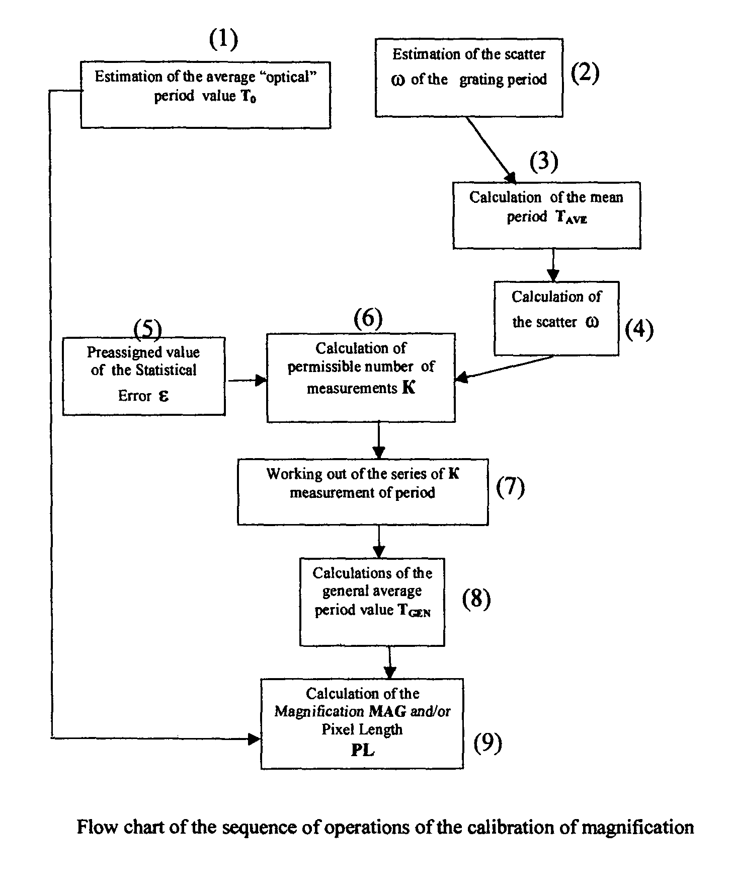
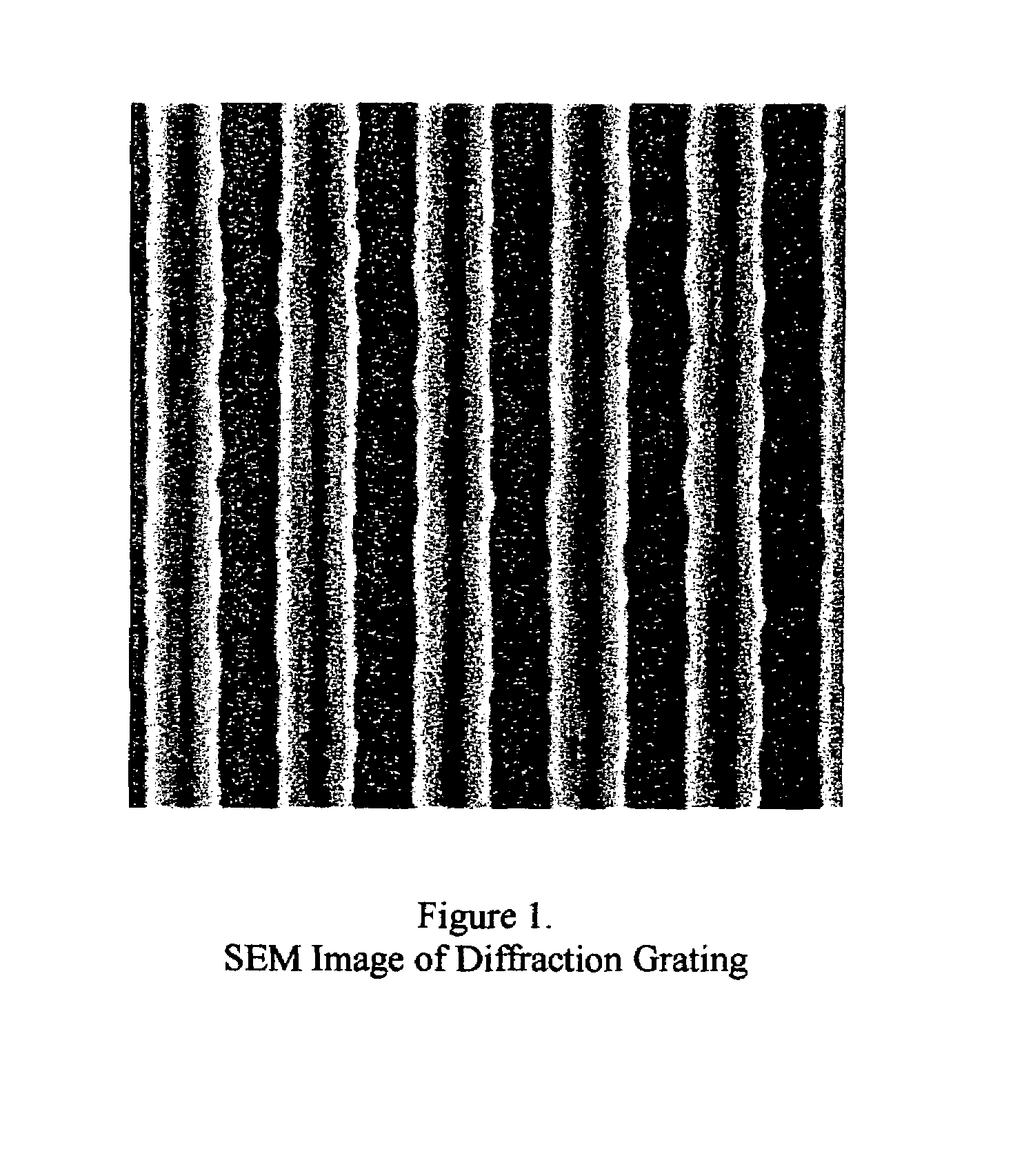
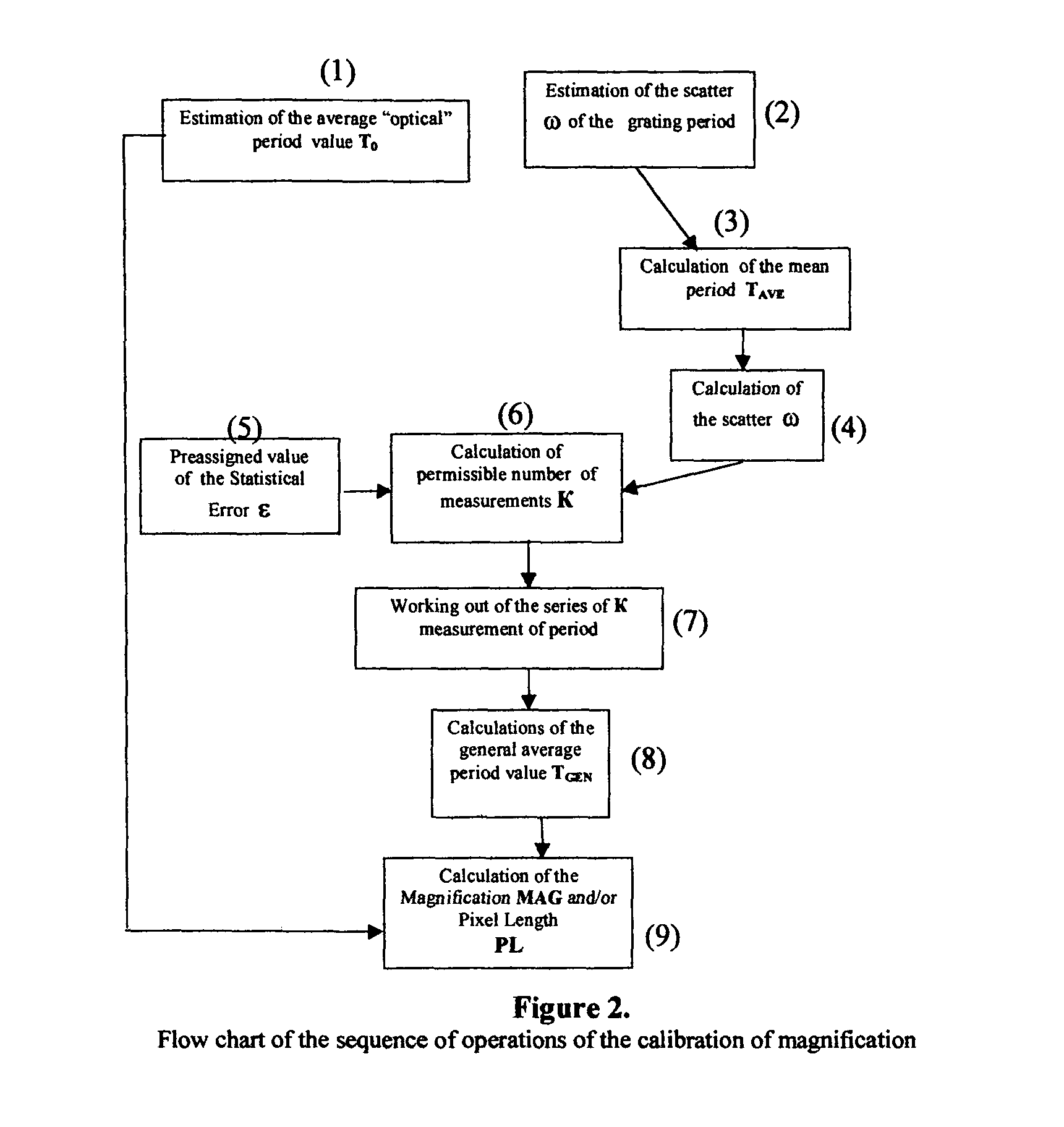
[0013]A method of calibration of magnification is illustrated for a measuring optical microscope or a scanning electron microscope or a probe microscope and is performed with the use of a diffraction grating (FIG. 1). The method includes first of all a measurement of a mean “optical” period T0 of the diffraction grating in a standard difractometric experiment, for example in accordance with the formula:

[0014]T0=m⁢⁢λsin⁢⁢θm

wherein m is an order of diffraction, λ is a wavelength of a used mono-chromatic radiation which is known with a high accuracy, and θm is an angle of diffraction measured in the experiment for the radiation which is diffracted in the m order.

[0015]Then scatter ω of individual values of periods of the test diffraction grating is determined. For this purpose multiple measurements of the period Ti with one of the known methods are performed. It is performed on images of different individual periods of the diffraction grating which are selected randomly, with their pos...


PUM


Abstract

A method of calibration of magnification of a microscope with the use of a diffraction grating has the steps of determining a mean period of a diffraction grating by irradiating the diffraction grating with an electromagnetic radiation having a known wavelength and analyzing a resulting diffraction pattern, determining a scatter of individual values of a period of the diffraction grating by multiple measurements of periods of the diffraction grating by a microscope in pixels in one area in a microscope field of view, and calculating a mean value of the period and the scatter based on the measurements, determining a sufficient number of measurements of the period for providing an accepted statistic error of a magnification of the microscope, performing measurements corresponding to the determined acceptable number of measurements, of individual values of the period in pixels in a plurality of portions of the diffraction grating, calculating a general mean value of the period in pixels based on the immediately preceding step, and finally calculating a parameter corresponding to the magnification of the microscope based on the determined mean value of the period of the diffraction grating in the microscope image and the calculating of the general mean value of the period in pixels.

Description

BACKGROUND OF THE INVENTION[0001]The present invention relates to methods of calibration of magnification of measuring microscopes.[0002]Measuring microscopes are used in different areas of science and industry for measurements of sizes of various objects which have sizes from inches to angstroms. There is no microscope which is capable to measure objects in such a broad range of sizes. For measurements in centimeter, millimeter and micrometer subranges, optical measuring microscopes are the most convenient microscopes. The subrange of micrometer and nanometer sizes is covered by scanning electron measuring microscopes. In the area of nanometer, sub-nanometer and atom (angstrom) sizes, probe microscopes are utilized, such as scanning tunnel microscopes and atomic force microscopes. There are objects with intermediate sizes, which can be measured by microscopes of one type or another type. Typical examples are the features of modern integrating circuits which have submicron and nanom...

Claims


Application Information

Patent Timeline
Patent Type & Authority Patents(United States)
IPC IPC(8): G01J1/10G01B9/04G02B21/00
CPCG02B21/00G01B9/04
Inventor NIKITIN, ARKADYSICIGNANO, ALBERTYEREMIN, DMITRIYGOLDBURT, TIM
Owner GEN PHOSPHORIX
Why Eureka
Try Eureka