
Interface transmitter for communications among network elements

a network element and interface technology, applied in the field of synchronous optical network (sonet) technology, can solve the problems of switching event detection and propagation problem further compounded, time allowed for propagation of switching event information among network elements is limited to a total of 50 milliseconds, and achieve the effect of avoiding delays associated with data collisions

Inactive Publication Date: 2006-05-30
CIENA
View PDF14 Cites 9 Cited by
  • Summary
  • Abstract
  • Description
  • Claims
  • Application Information

AI Technical Summary

Benefits of technology

[0013]The TS Net provides switching event information among TMO switch cards in a TS Net data frame transferred over a separate TS Net backplane so as to avoid delays associated with data collisions. The TS Net couples the outputs of the switch cards of a TMO switch to the input of each switch card using a number of backplane communication channels. The backplane communication channels form a bus that is coupled to the input of all switch cards. Switching event information from each switch card in the form of K1 / K2 bytes, along with the E1 / F1 bytes and card status information, are assembled into the TS Net data frame. The TS Net data frame includes a payload of 67.5 bytes transmitted as a serial bit stream at 4.32 MHz. The TS Net data frame is transferred among all TMO switch cards using the backplane communication channels or bus.
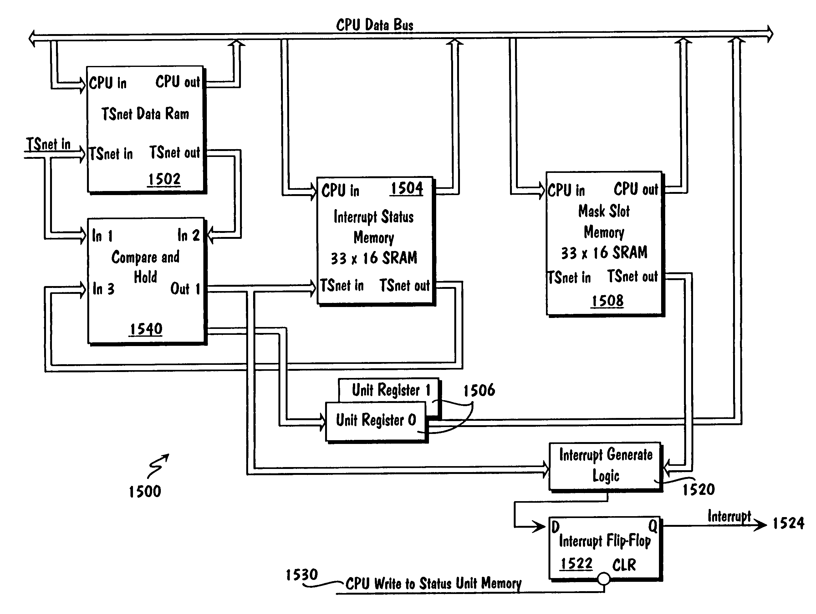
[0014]The TS Net data frame payloads are stored in a number of memory areas using multiple level data storage and mapping. At prespecified intervals, compare operations are performed among subsequently received net data frame payloads and the stored payloads of previous TS Net data frames. A unit interrupt is generated by a switch card in response to a detected switching event, as indicated by a bit change or bit inequality in at least one byte of the compared TS Net data frames during the compare operation. Further, a massive interrupt is generated in response to a unit interrupt in any switch card. In response to the massive interrupt, a TMO switch processor is directed to the memory location containing the detailed switching event data using a multiple level read operation, wherein the processor is efficiently directed through multiple TS Net data memory areas or partitions. The switching event data is evaluated and the switching event dealt with accordingly, thereby minimizing response time in the performance of protection switching over that in typical SONET systems.

Problems solved by technology

A problem arises in SONET ring protection switching in that the time allowed for propagation of switching event information among network elements is limited to a total of 50 milliseconds.
Typically, numerous switching events can be occurring simultaneously in a number of network elements as a result of a single switching event propagating along the network and adversely affecting many network elements.
As such, the propagation time problem is compounded.
The switching event detection and propagation problem is further compounded by the control structure of a typical SONET ring.
The problem arises in that, as numerous network elements are typically receiving the switching event information at about the same time, a number of network elements are communicating with the processor hub regarding the switching event information at about the same time.
This leads to information collisions in the processor hub.
As a result of these information collisions, the propagation time limits are often violated in typical rings.
However, the switched mode is much more expensive and space consuming because it requires more processing power and additional space to implement the switch logic.
As there is a need to reduce the expense and physical size of the SONET equipment, the switched mode would not provide a viable solution.
This, too, is problematic in that the bus requires more interconnection among nodes and results in an architecture where a single point failure is fatal.
As such, a bus fault would result in a system failure.
While a dual redundant bus might prevent the single point of failure, it requires significantly more interconnection among nodes and introduces a complex control system.
Further, a massive interrupt is generated in response to a unit interrupt in any switch card.

Method used


Image

  • Interface transmitter for communications among network elements
  • Interface transmitter for communications among network elements
  • Interface transmitter for communications among network elements

Examples


Embodiment Construction

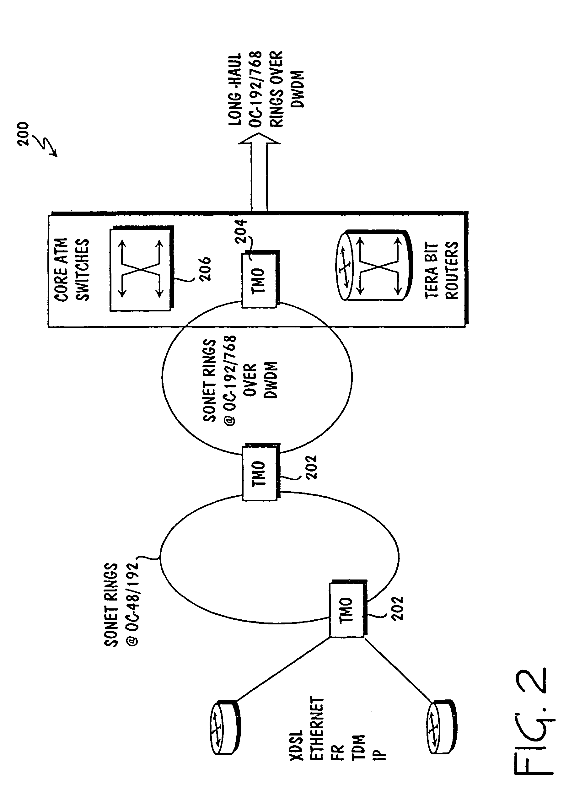
[0046]The Trans-Metro Optical (TMO) switch system of an embodiment uses a non-binding architecture that includes integrating discrete subsystems including SONET network elements with a backplane and interchangeable line cards. In addition to performing digital cross-connect (DCS) and add-drop multiplexer (ADM) functions with a common card, the TMO switches support the typical packet and circuit transport protocols. Packet support encompasses asynchronous transfer mode (ATM) service access multiplexers / switches, frame relay (FR) access switches, and multi-protocol label and internet protocol (IP) (MPLS / IP) switches. Circuit switching support is provided for voice and private line point-to-point circuits. Consequently, the TMO switch provides a data optimized SONET platform which integrates SONET ADMs, DCSs and ATM / FR switch functionality into a single platform.

[0047]The typical metropolitan area network (MAN) hierarchy is a mix and match of SONET sub-networks, subsystems, protocols, ...


PUM


Abstract

An interface transmitter coupled among a number of network elements of at least one network is provided, wherein a number of data frames of a first type are received from at least one processor and stored in at least one random access memory (RAM). Data is read from the RAM to at least one data serializer in response to a number of signals received from the processor and over at least one backplane network. A number of data frames of a second type corresponding to the data frames of a first type are generated and serially transferred among the network elements using the backplane network.

Description

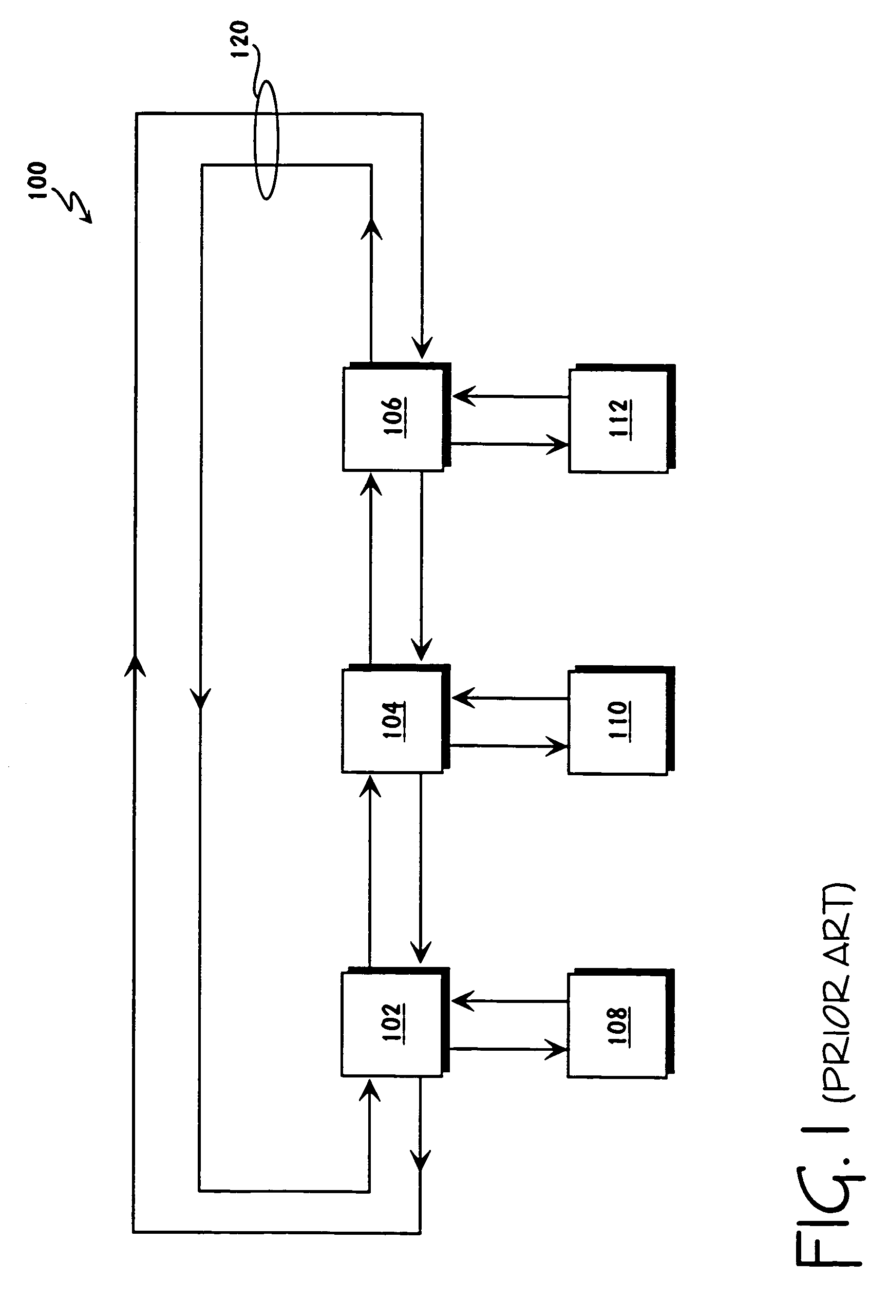
BACKGROUND[0001]1. Field of the Invention[0002]This invention relates to the field of Synchronous Optical Network (SONET) technology. In particular, the invention relates to increasing the efficiency of SONET communications by minimizing the response time for the performance of protection switching.[0003]2. Description of the Related Art[0004]Synchronous Optical Networks (SONET) are fiber-optic transmission systems for high-speed digital traffic. The SONET technology is an intelligent system that provides advanced network management and a standard optical interface. The SONET technology is typically deployed in SONET rings that originate and terminate in a carrier's facility. FIG. 1 is a typical simple SONET ring 100. While SONET networks or rings can be quite complex, the typical SONET network 100 includes numerous network elements 102–112 linked by upstream and downstream communication fibers 120. A ring 100 may span only a few miles or stretch thousands of miles, depending on its...

Claims


Application Information

Patent Timeline
IPC IPC(8): H04L12/56
CPCH04L49/30H04L2012/5665H04L49/555H04L49/357
Inventor BEN-ZUR, RAANANWANG, SHI-WOANGSHARMA, AVINISH KUMAR
Owner CIENA
Learn More