Clock control method, frequency dividing circuit and PLL circuit

a control method and frequency division technology, applied in the field of frequency dividing circuit and phaselocked loop, can solve the problems of large amount of power consumption, difficult control of the timing of the mc (modulus control) signal, and difficulty in high-speed operation, so as to facilitate timing design and reduce power consumption

Inactive Publication Date: 2006-05-30
RENESAS ELECTRONICS CORP
View PDF6 Cites 30 Cited by
  • Summary
  • Abstract
  • Description
  • Claims
  • Application Information

AI Technical Summary

Benefits of technology

[0030]Accordingly, it is an object of the present invention to provide a variable frequency dividing circuit that reduces power consumption and facilitates design of timing, a PLL circuit equipped with this frequency dividing circuit, and a method of clock control.

Problems solved by technology

In addition, a large amount of power is consumed owing to the parallel arrangement of the A counter and B counter constituting the programmable counters.
Furthermore, it is difficult to control the timing of the MC (modulus control) signal, which is the signal that controls the changeover of the number of frequency divisions of the dual modulus prescaler.
As a consequence, high-speed operation is difficult.
This makes it difficult to place the prescaler and control circuit on separate chips, thereby limiting freedom of circuit design.

Method used


Image

  • Clock control method, frequency dividing circuit and PLL circuit
  • Clock control method, frequency dividing circuit and PLL circuit
  • Clock control method, frequency dividing circuit and PLL circuit

Examples


Embodiment Construction

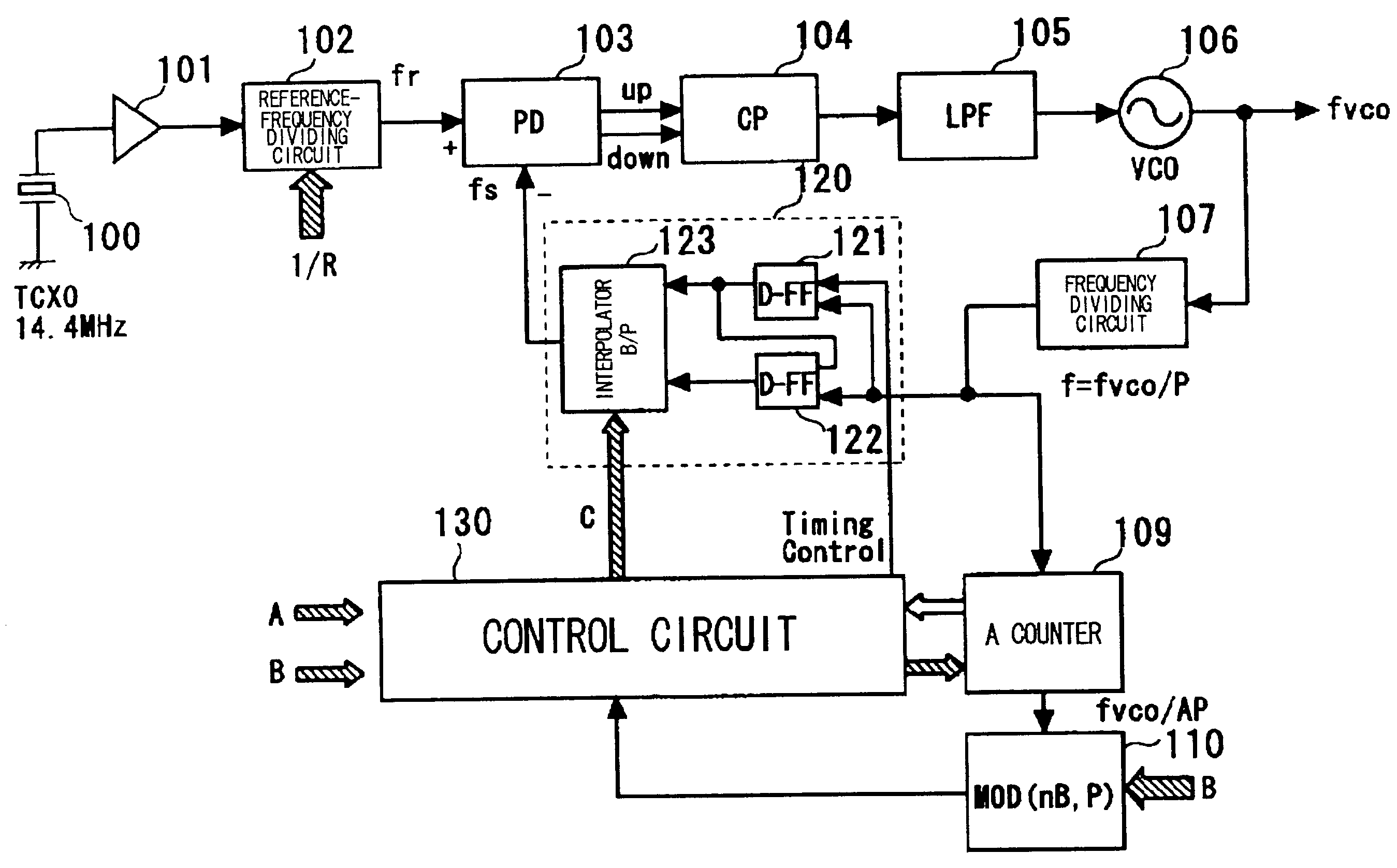
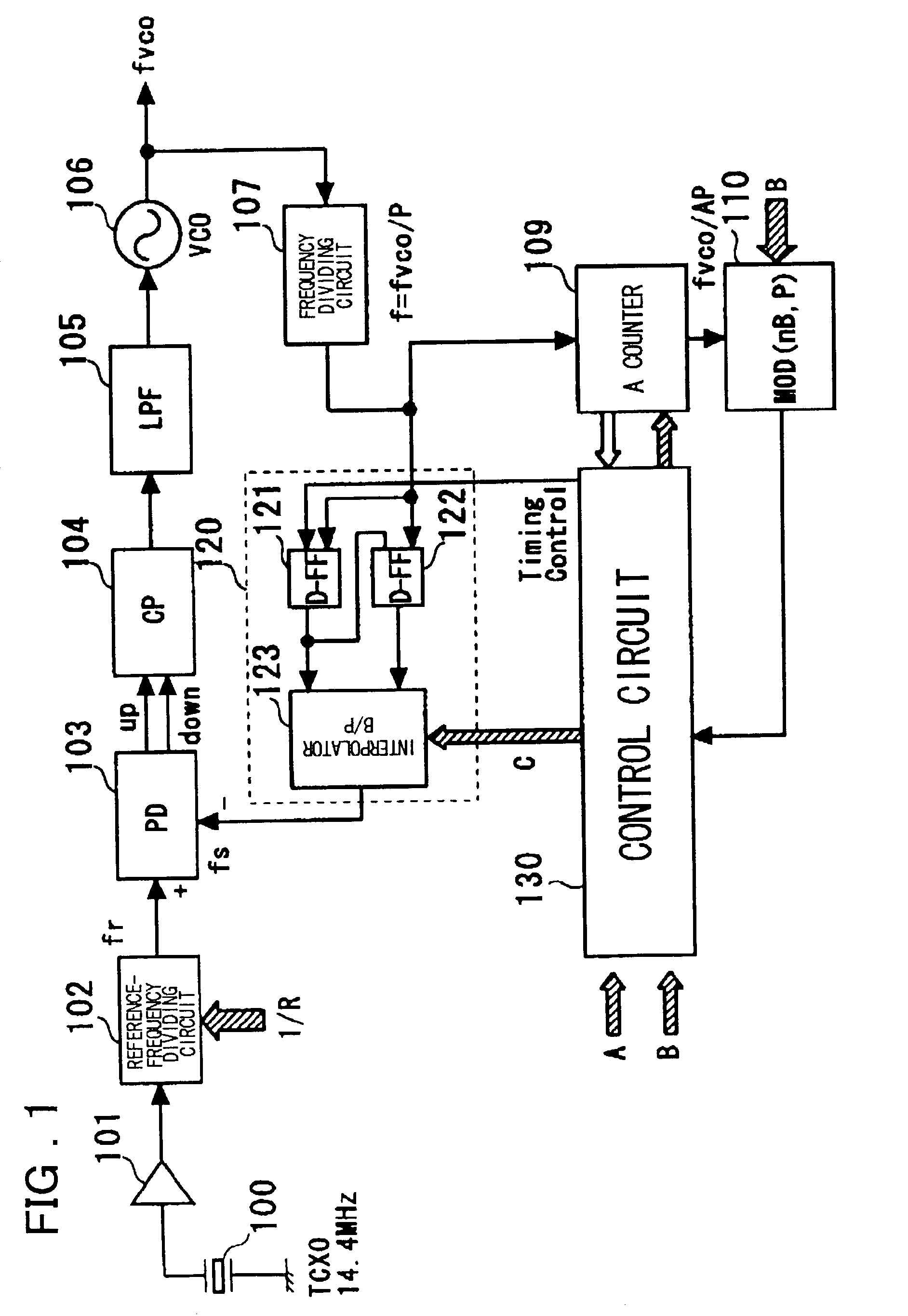
[0052]Preferred embodiments of the present invention will now be described. As shown in FIG. 1, a frequency dividing circuit in accordance with a preferred embodiment of the present invention includes a first frequency dividing circuit (107) for performing frequency-division of an input signal by P (where P is a positive integer); a second frequency dividing circuit (109) for performing frequency-division of an output signal of the first frequency dividing circuit (107) by A (where A is a positive integer); a circuit (121, 122, 130) for generating two signals, which have a phase difference equivalent to one period of the P-frequency-divided output of the first frequency dividing circuit (107), whenever frequency-division by A is performed by the second frequency dividing circuit (109); an interpolator (123), which receives the two generated signals, for generating and outputting an output signal of a phase obtained by interpolating the phase difference between the two signals in ste...


PUM


Abstract

A PLL circuit includes a phase comparator; a charge pump; a loop filter; a voltage-controlled oscillator; a frequency dividing circuit; an A counter for dividing the P-frequency-divided output; circuits for generating two signals, which have a phase difference equivalent to one period of the P-frequency-divided output of the frequency dividing circuit; and an interpolator for producing an output signal obtained by interpolating the phase difference between the two signals in accordance with an interior division ratio. The interpolator interpolates in steps of a value obtained by dividing the phase difference by P and incrementing or decrementing a value B, which decides an interior division ratio B:P−B, by B whenever frequency-division by A is performed, and a control circuit. The phase of the output of the interpolator is fed to the phase comparator and compared with the phase of a reference clock, and divides by a frequency-dividing factor.

Description

FIELD OF THE INVENTION[0001]This invention relates to a frequency dividing circuit and to a phase-locked loop (PLL) equipped with the frequency dividing circuit. More particularly, the invention relates to a variable frequency dividing circuit that employs an interpolator, and to a PLL having this frequency dividing circuit.BACKGROUND OF THE INVENTION[0002]FIG. 14 is a diagram illustrating the structure of a conventional PLL equipped with a variable frequency divider has pulse-swallow architecture.[0003]As shown in FIG. 14, the PLL comprises an amplifier 201 for amplifying the output (whose frequency ftcxo is 14.4 MHz) of an externally mounted temperature-compensated crystal oscillator (TCXO) 200; a reference-frequency dividing circuit 202 for frequency-dividing the output of the amplifier 201; a phase comparator 203 for sensing the phase difference between a reference signal (frequency f≈400 KHz), which is the result of frequency division by the reference-frequency dividing circuit...

Claims


Application Information

Patent Timeline
Patent Type & Authority Patents(United States)
IPC IPC(8): H03D3/24G06F1/08G06F7/68H03K5/00H03K23/64H03L7/08H03L7/081H03L7/089H03L7/183H03L7/197
CPCG06F7/68H03L7/1976H03L7/1974H03L7/081H03K2005/00065H03K2005/00071H03L7/0891
Inventor SAEKI, TAKANORI
Owner RENESAS ELECTRONICS CORP
Why Eureka
Try Eureka