Frequency comparator with malfunction reduced and phase-locked state detecting circuit using the same

a technology of phase-locked state and frequency comparator, which is applied in the direction of multiple input and output pulse circuits, digital transmission, instruments, etc., can solve the problems of large jitter error of frequency comparator with respect to data signal with large jitter, control signal up or down is erroneously output,

Inactive Publication Date: 2003-09-25
MITSUBISHI ELECTRIC CORP
View PDF6 Cites 4 Cited by
  • Summary
  • Abstract
  • Description
  • Claims
  • Application Information

AI Technical Summary

Problems solved by technology

However, in the case where jitter is .+-.90.degree. or larger with respect to, for example, the phase of the clock, even in the phase-locked state, there is the possibility that the data edge is positioned in the region B or C. I

Method used


Image

  • Frequency comparator with malfunction reduced and phase-locked state detecting circuit using the same
  • Frequency comparator with malfunction reduced and phase-locked state detecting circuit using the same
  • Frequency comparator with malfunction reduced and phase-locked state detecting circuit using the same

Examples


Embodiment Construction

[0050] An embodiment of the invention will be described in detail hereinafter with reference to the drawings. The same reference numeral in the drawings denotes the same or corresponding component.

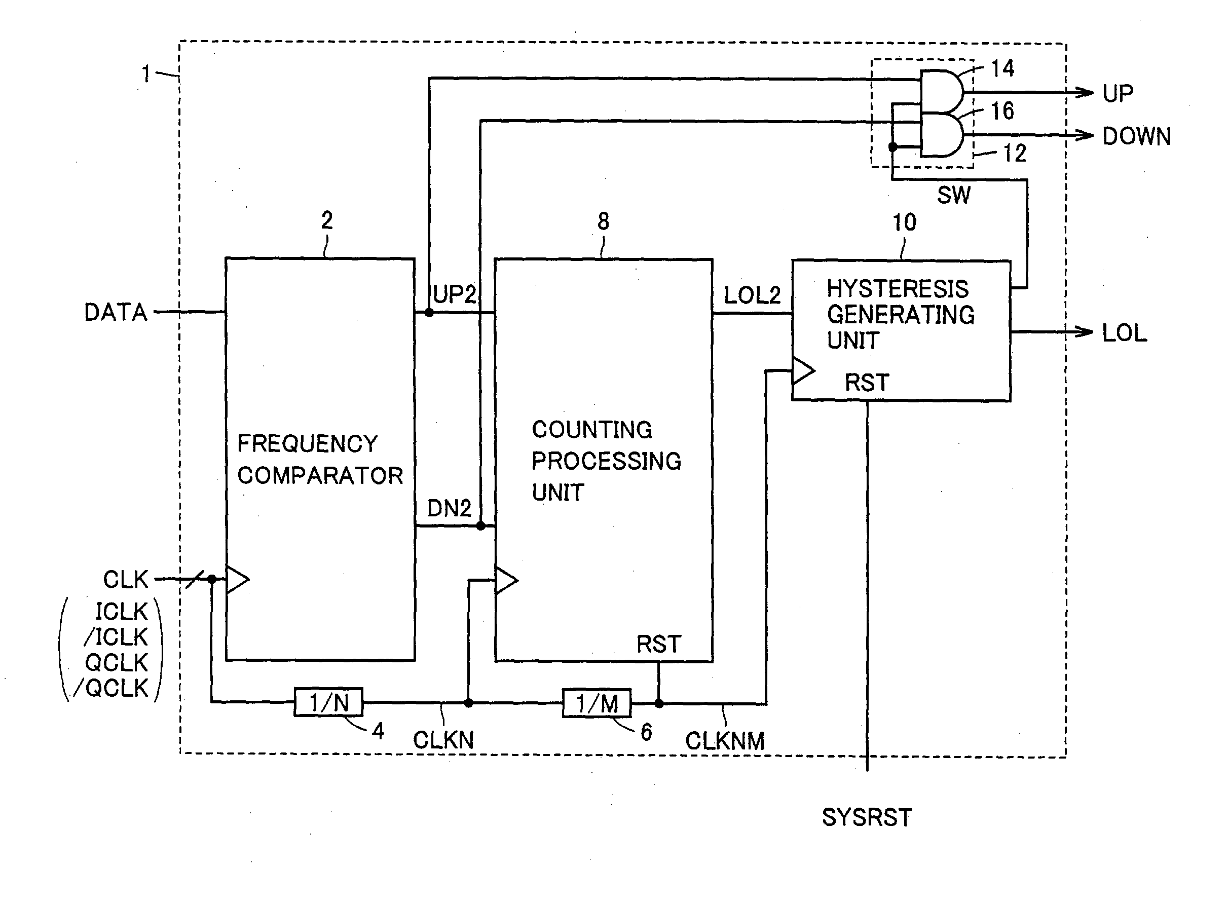
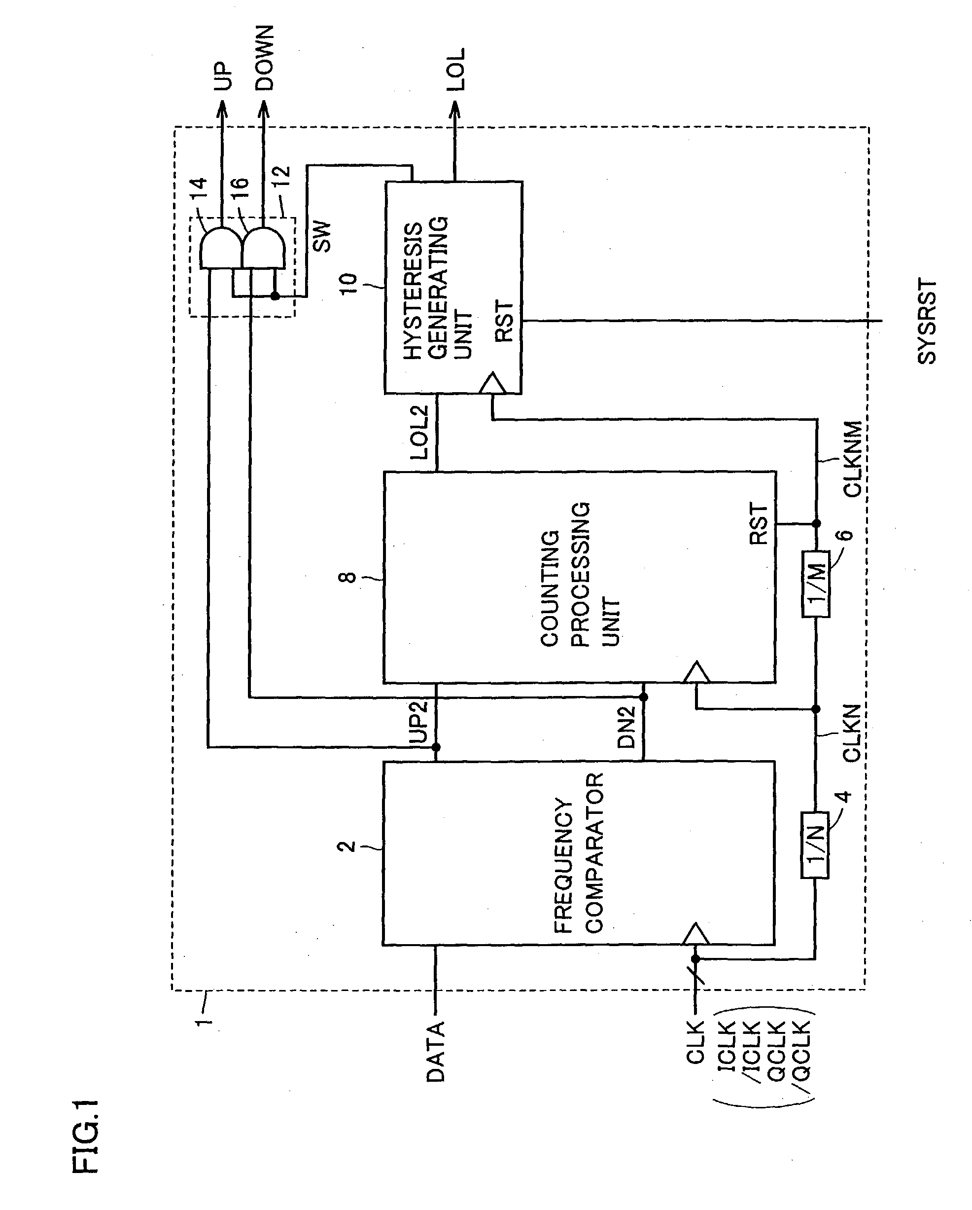
[0051] FIG. 1 is a schematic block diagram showing the configuration of a phase-locked state detecting circuit 1 in the embodiment of the invention.

[0052] Referring to FIG. 1, phase-locked state detecting circuit 1 includes: a frequency comparator 2 for comparing the phase of a clock signal CLK of four phases which are different from each other by 90.degree. with that of a data signal DATA and outputting a control signal UP2 or DN2; a counting processing unit 8 for counting up control signals UP2 and DN2 and detecting an overflow of a predetermined count value; a frequency dividing unit 4 for dividing clock signal CLKN to 1 / N, thereby outputting a clock signal CLKN; a frequency dividing unit 6 for further dividing clock signal CLKN to 1 / M, thereby outputting a clock signal CLKNM; a hystere...


PUM


Abstract

A frequency comparator detects the phase of a data signal DATA by using four-phase clocks ICLK, /ICLK, QCLK and /QCLK as a reference and detects a change in the phase. A counting processing unit counts a period in which a control signal UP2 or DN2 is activated within a predetermined period, and outputs an overflow detection signal LOL2 if the frequency is high. A hysteresis generating unit changes a signal LOL to the L level only after signal LOL goes low X times consecutively. On the other hand, after signal LOL is set to the L level once, the hysteresis generating unit changes signal LOL to the H level only after signal LOL2 goes high X times consecutively. With such a configuration, a phase-locked state detecting circuit with reduced malfunction even when a data signal having larger jitter is input can be provided.

Description

[0001] 1. Field of the Invention[0002] The present invention relates to a frequency comparator with a malfunction reduced at the time of performing frequency comparison on a data signal having large jitter, and a phase-locked state detecting circuit using the same.[0003] 2. Description of the Background Art[0004] A circuit for comparing the frequency of an input signal from the outside of a chip with the frequency of an internal clock generated by an internal oscillator is called a frequency comparator. The frequency comparator outputs a control signal DOWN when the frequency of the internal clock is high and outputs a control signal UP when the frequency of the internal clock is low. The frequency comparator is used for a control of optimizing the frequency of the internal oscillator with respect to a signal input from the outside.[0005] FIG. 16 is a circuit diagram showing the configuration of a conventional frequency comparator 500.[0006] Referring to FIG. 16, frequency comparato...

Claims


Application Information

Patent Timeline
IPC IPC(8): H03K5/26H03D13/00H03L7/089H03L7/095H04L7/02
CPCH03D13/004
Inventor YOSHIMURA, TSUTOMU
Owner MITSUBISHI ELECTRIC CORP
Why Eureka
Try Eureka