Method and device for processing analogue output signals from capacitive sensors

a capacitive sensor and output signal technology, applied in the field of reading out of sensors, can solve the problems of inability to realize reasonable digital signal processing with current digital signal processors, limited sensor output signals, and demodulation of sensor signals, so as to reduce the noise of electronic circuits, no data loss, and no additional noise

Inactive Publication Date: 2006-05-30
HAHN SCHICKARD GESELLSCHAFT FUER ANGEWANDTE FORSCHUNG EV
View PDF20 Cites 31 Cited by
  • Summary
  • Abstract
  • Description
  • Claims
  • Application Information

AI Technical Summary

Benefits of technology

[0016]Based on the prior art it is the object of the present invention to provide an improved concept for processing an output signal of a sensor in order to improve the measurement accuracy and sensitivity of a sensor arrangement.
[0019]The present invention is based on the findings that the processing of a sensor output signal of a sensor element, like e.g. a capacitive rotational rate sensor, may be significantly improved by the use of a digital processing technique.
[0028]Due to the possibility to be able to perform the processing of a sensor output signal of a sensor element using a signal processor basically digitally, a plurality of advantages result.
[0033]The actual information (bit combination proportional to the rotational rate) is digitally output from the digital signal processor or may be further processed as a PWM signal (PWM=pulse width modulation) so that with a possible D / A conversion of the useful signal no data losses and no additional noise, respectively, must be accepted. With this method the noise of the electronic circuit may be reduced and the actual resolution capability of the sensor may almost be achieved.
[0035]If for example several rotational rate sensors are used together in different angle positions, the movement and the velocity of an object may be determined. Therefore, low-cost, low-interference (i.e. extremely reliable) and smallest rotational rate sensors may be realized for specific tailor-made industrial applications by micro-mechanical manufacturing processes. With the inventive digital read out and evaluation method, for example rotation movements up to a range of about 0.01° per second may be detected for capacitive rotational rate sensors.
[0036]Due to the reduced signal processing requirements to the digital signal processors which are used in the present invention for sensor signal evaluation, it is possible, that the same take over additional tasks and functions for each individual sensor or for the overall system, like for example an active temperature compensation with the help of PI regulators, a self-calibration and a self-diagnosis function.

Problems solved by technology

In micro-mechanical rotational rate sensors this sensor output signal is mainly limited by the noise of the electronic components of the evaluation electronic, as the actual information which is contained within the sensor output signal of the rotational rate sensor may generally not be differentiated from noise below a certain level and may then not be detected anymore.
A major problem referring to this arrangement is, that the first demodulation of the sensor signal has to be performed with the high-frequency carrier signals (e.g. 500 kHz).
In an oversampling of the carrier signals, a digital signal processor therefore had to work with a clock frequency which is higher than double the carrier frequency, which may not be realized reasonably with current digital signal processors due to the very extensive calculation operations that would occur.
A further problem regarding the above-described conventional sensor arrangement is, that in addition to the inherent noise of the first (analog) operation amplifier 322 further noise proportions and among others temperature drift is introduced into the useful signal by the electronic evaluation components, whereby the resolution and therefore the sensitivity and measurement accuracy of the sensor arrangement is affected significantly.
This therefore leads to an operation performance in processing an output signal of a capacitive sensor arrangement which is not optimum.

Method used


Image

  • Method and device for processing analogue output signals from capacitive sensors
  • Method and device for processing analogue output signals from capacitive sensors
  • Method and device for processing analogue output signals from capacitive sensors

Examples


Embodiment Construction

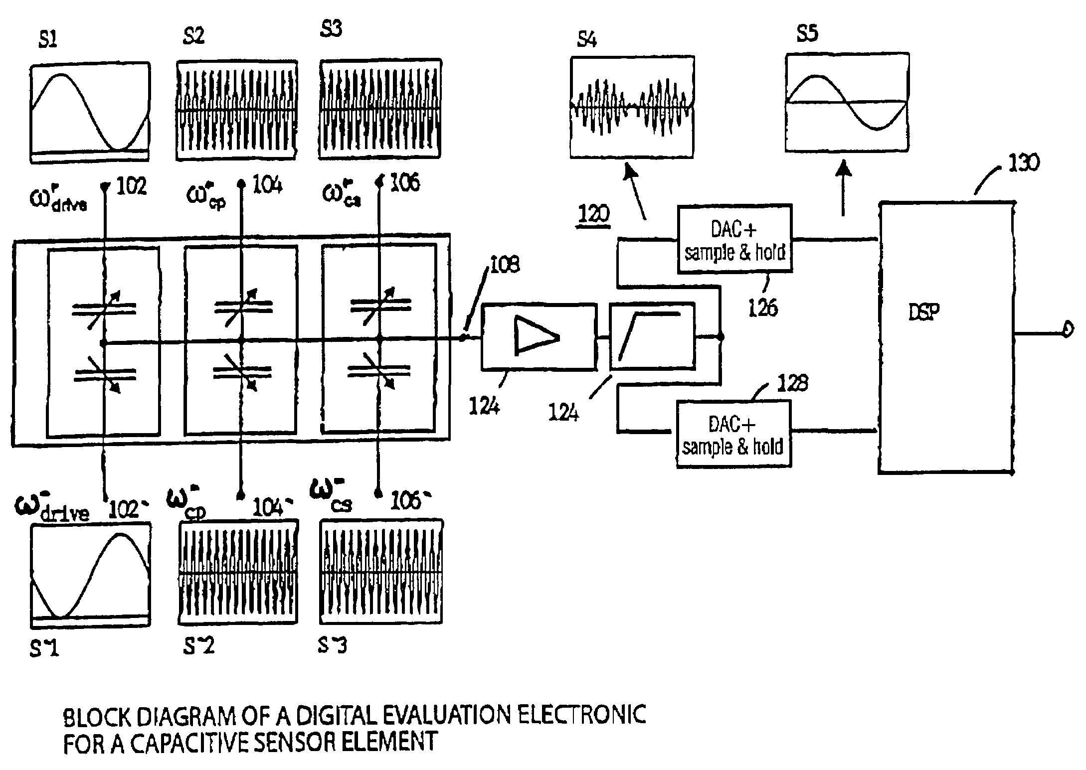
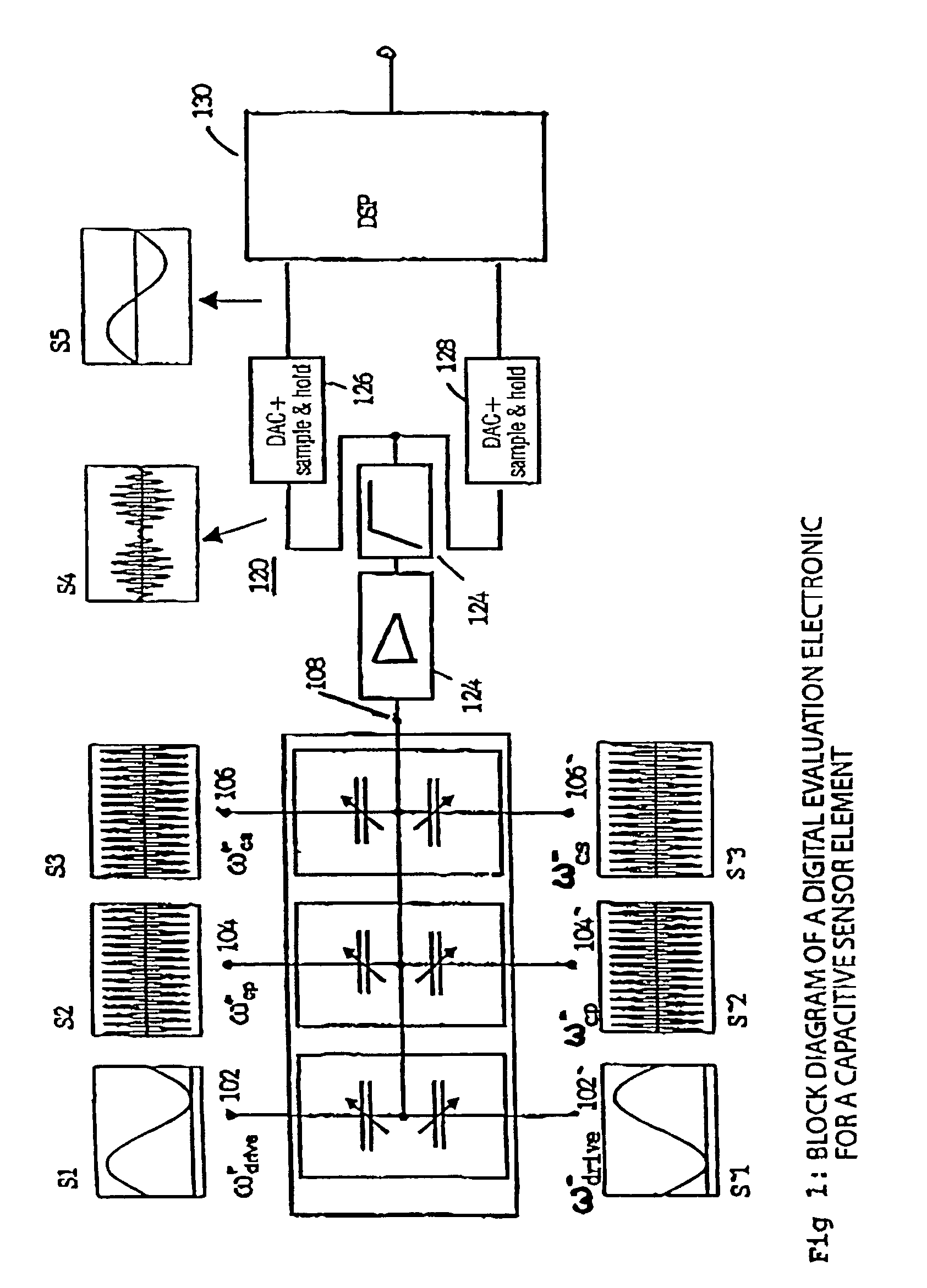
[0044]FIG. 1 shows the block diagram of digital read out and evaluation electronics 120 for a sensor arrangement 100 according to the present invention. The capacitive sensor element 100 corresponds to the sensor element 300 of FIG. 3 which was already discussed in the description introduction. In the following description of the present invention, for explaining the inventive concept reference is made to capacitive sensor elements, like e.g. to micro-mechanical rotational rate sensors, which use the Coriolis force for determining a rotational rate to be detected.

[0045]The capacitive sensor element 100 schematically illustrated in FIG. 1 comprises three input electrode pairs, wherein at the driver input electrode pair 102, 102′ driver input signals S1, S′1 with the frequency ω+drive, ω−drive are applied, at the electrode pair 104, 104′ primary carrier signals S2, S′2 with the frequency ω+cp, ω−cp are arranged, and at the electrode pair 106, 106′ secondary carrier signals S3, S′2 wit...


PUM


Abstract

An analogue output signal of a sensor which comprises a carrier signal with a carrier frequency ωC which is modulated by a measurement size is sampled with a sampling frequency ωA to receive a sampled sensor output signal. The frequency ωA of the sampling signal is set so that it is an integer divisor n of the carrier frequency ωC, wherein the phase of the sampling signal is set so that the sampling signal is synchronous to the sensor output signal. The sampled sensor output signal is filtered now to remove periodically repeated signal components from the sampled sensor output signal. Then a filtered useful signal is received, wherein its amplitude is proportional to the measurand detected by the sensor.

Description

BACKGROUND OF THE INVENTION[0001]1. Field of the Invention[0002]The present invention relates to the reading out of sensors and in particular to the digital processing of senor output signals comprising a high-frequency carrier signal which is modulated by a measured value. In the following description of the present invention reference is made to capacitive sensors for discussing the inventive concept, like for example to micro-mechanical rotational rate sensors which use the Coriolis power for determining a rotational rate to be detected.[0003]2. Description of the Related Art[0004]Capacitive sensors, like for example micro-mechanical rotational rate sensors, have a variety of application opportunities. Thus, micro-mechanical rotational rate sensors are for example used in robots and mounting systems, in medical technology, in cameras for image stabilizing, in navigation systems, for stabilizing and remote-controlling road and air vehicles and also in airbag and protection systems...

Claims


Application Information

Patent Timeline
Patent Type & Authority Patents(United States)
IPC IPC(8): G01R27/28G01C19/56
CPCG01C19/5776
Inventor GEIGER, WOLFRAMGAISSER, ALEXANDERNIKLASCH, NORBERT
Owner HAHN SCHICKARD GESELLSCHAFT FUER ANGEWANDTE FORSCHUNG EV
Why Eureka
Try Eureka