Deposition fabrication using inkjet technology

a technology of inkjet printing and deposition, applied in the field of inkjet printing, can solve problems such as plating and etching, and achieve the effects of greater precision and density, and small area

Active Publication Date: 2006-06-06
LEXMARK INT INC
View PDF28 Cites 26 Cited by
  • Summary
  • Abstract
  • Description
  • Claims
  • Application Information

AI Technical Summary

Benefits of technology

[0007]The present invention is directed to inkjet printing, and more specifically to inkjet printing utilizing conductive ink deposition to fabricate conductive patterns upon a filtered substrate. The present invention includes methods, and devices manufactured using such methods, for fabricating RFID tags, and more specifically, RFID antennae. The present invention makes use of conductive inks comprising a carrier fluid and suspended conductive particles that are ejected onto a printable medium to create conductive patterns. The present invention incorporates substrates having channels adapted to draw away the carrier fluid from the surface of the substrate to leave behind the conductive particles on the surface. In this manner, a droplet of conductive ink spreads over a smaller area than using conventional substrates and allows for greater precision and density in depositing the conductive particles. Exemplary substrates for use with the present invention may be subjected to a vacuum or elevated temperature environment to dry the conductive particles and stabilize the positioning of the particles on the substrate surface.
[0016]It is a fifth aspect of the present invention to provide a method of accurately and precisely depositing conductive particles of a conductive ink from an inkjet printer, the method comprising: (a) orienting a substrate with respect to an inkjet printer, the substrate including a plurality of generally aligned interstices adapted to filter a conductive ink; (b) depositing the conductive ink upon the substrate in a predetermined pattern using the inkjet printer, where the conductive ink comprises conductive particles and a carrier fluid; and (c) drying the conductive particles to mount the conductive particles upon a surface of the substrate and provide a conductive antenna.

Problems solved by technology

Present day methods of manufacturing RFID antennae include costly plating and etching processes similar to current semiconductor device manufacturing techniques.

Method used


Image

  • Deposition fabrication using inkjet technology
  • Deposition fabrication using inkjet technology
  • Deposition fabrication using inkjet technology

Examples


Embodiment Construction

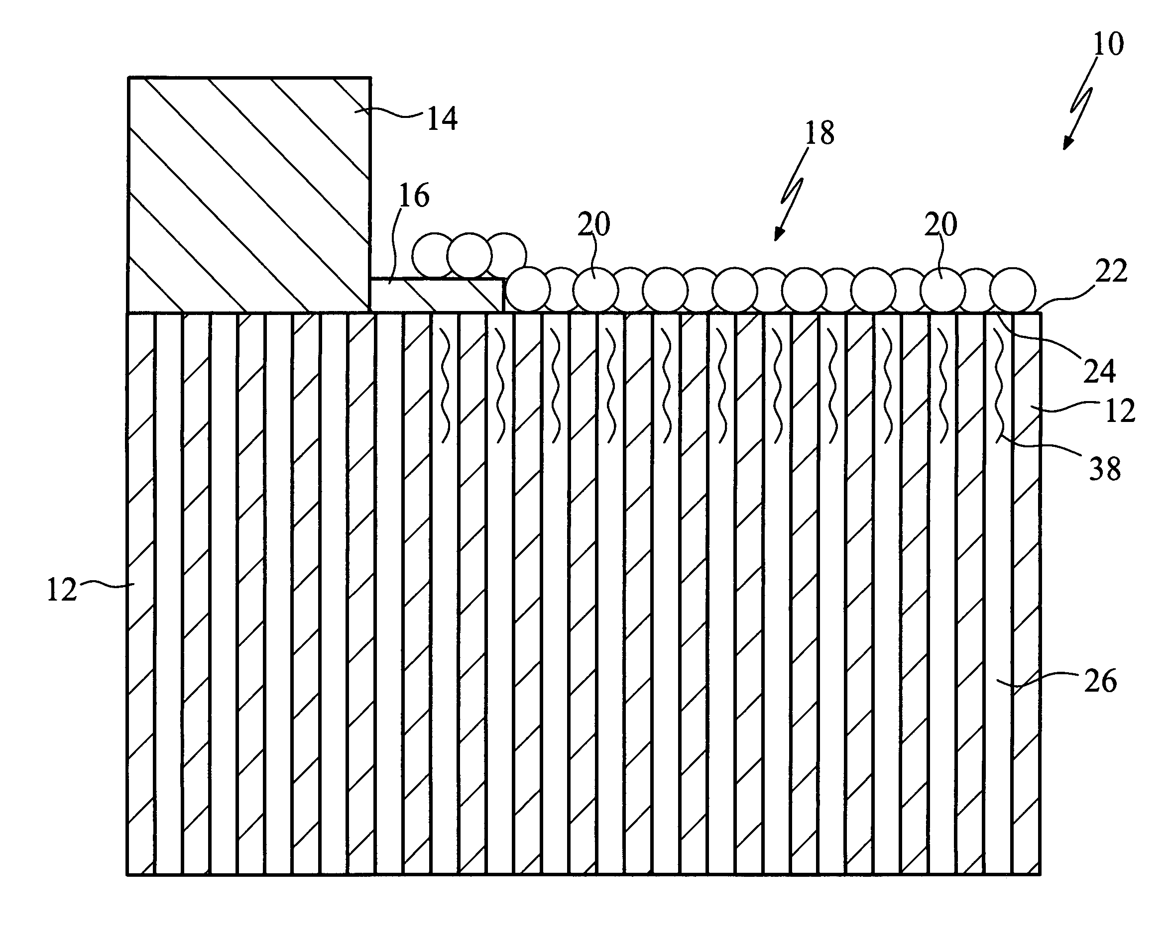
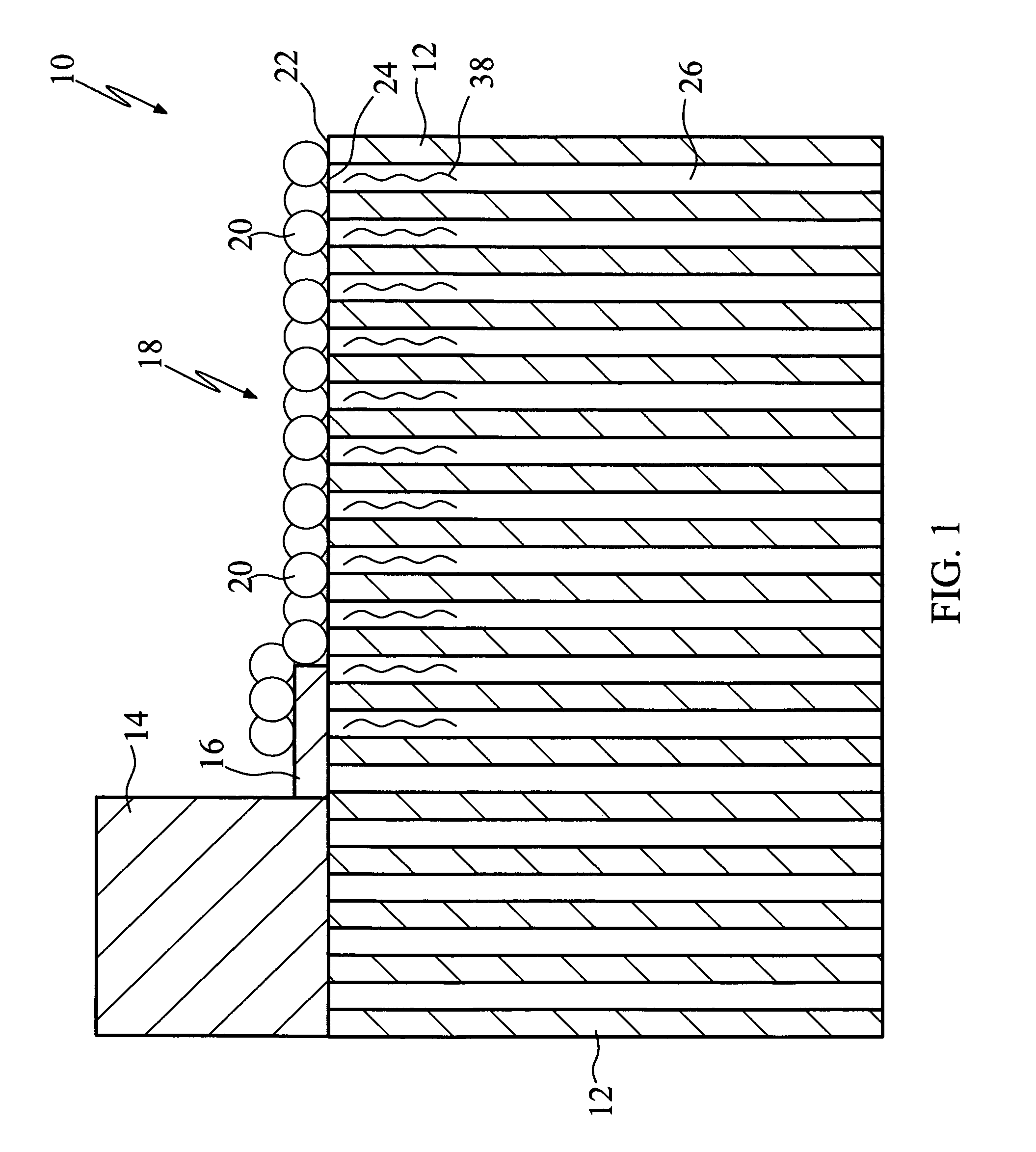
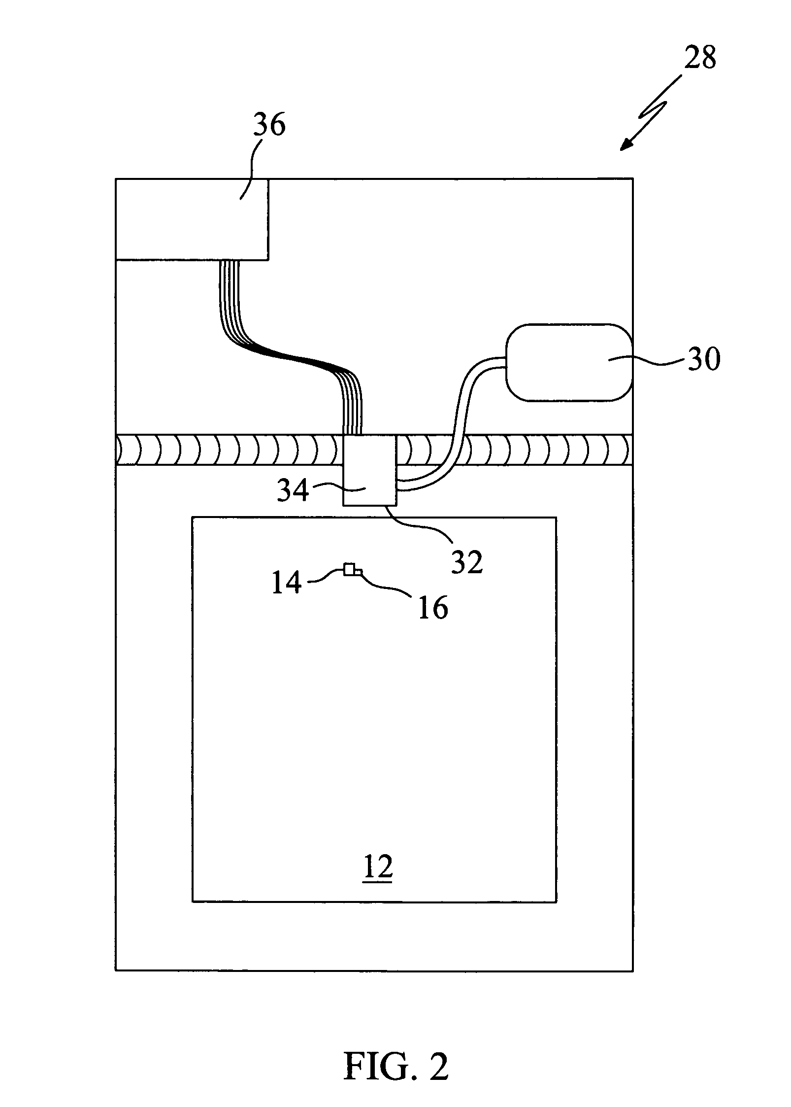
[0020]The exemplary embodiments of the present invention are described and illustrated below to encompass methods, and devices produced in accordance with such methods, for depositing conductive materials upon a filtered substrate. Of course, it will be apparent to those of ordinary skill in the art that the preferred embodiments discussed below are exemplary in nature and may be reconfigured without departing from the scope and spirit of the present invention. In addition, those of ordinary skill will readily comprehend various devices that may be fabricated in accordance with the methods discussed herein and, therefore, the disclosure is not limited to the exemplary embodiments discussed herein, as these embodiments are for purposes of illustrating the invention only. However, for clarity and precision, the exemplary embodiments as discussed below may include optional steps or features that one of ordinary skill will recognize as not being a requisite to fall within the scope of t...


PUM

PropertyMeasurementUnit
mean diameteraaaaaaaaaa
conductiveaaaaaaaaaa
microporesaaaaaaaaaa

Abstract

A method of fabricating an RFID antenna, the method comprising: (a) depositing a slurry upon a substrate in a predetermined pattern, the substrate including a plurality of micropores operative to drain a fluid component of the slurry from the surface of the substrate, while maintaining conductive particles of the slurry on a surface of the substrate; and (b) drying the conductive particles to secure the conductive particles upon a surface of the substrate and provide a conductive antenna. The invention also includes an RFID tag comprising: (a) a substrate including a plurality of micropores; (b) a microchip; and (c) an RFID antenna in electrical communication with the microchip and contacting the substrate, the RFID antenna comprising conductive particles deposited upon the substrate by ejecting a slurry from an inkjet printer.

Description

BACKGROUND[0001]1. Field of the Invention[0002]The present invention is directed to inkjet printing, and more specifically to inkjet printing utilizing conductive ink deposition to fabricate conductive patterns upon a filtered substrate.[0003]2. Background of the Invention[0004]Radio Frequency Identification (RFID) tags have been developed and envisioned to replace the bar code as the preeminent future identification tool. Present day methods of manufacturing RFID antennae include costly plating and etching processes similar to current semiconductor device manufacturing techniques.[0005]RFID is an automatic identification technology whereby digital data encoded in an RFID tag or “smart label” is captured by a reader using radio waves and, therefore, RFID does not require the tag or label to be visually apparent in order to read its stored data. An RFID system consists of a tag, which is made up of a microchip with an antenna, and a reader with an antenna. The reader sends out electr...

Claims


Application Information

Patent Timeline
Patent Type & Authority Patents(United States)
IPC IPC(8): G06K19/06H05K1/03H05K1/05
CPCH05K3/1208H05K3/125Y10T436/209163H05K2203/013Y10T428/24802H05K2201/0116
Inventor ANDERSON, FRANK E.GUAN, YIMIN
Owner LEXMARK INT INC
Why Eureka
Try Eureka