Cooled insulation surface temperature control system

a surface temperature control and cooling insulation technology, applied in the direction of cosmonautic thermal protection, lighting and heating apparatus, cosmonautic vehicles, etc., can solve the problems of increasing the cost and complexity of the plenum, reducing the heat transfer at the plenum outer wall, and correspondingly poor surface temperature control. to achieve the effect of preventing the erosion of the porous layer

Inactive Publication Date: 2006-06-06
THE BOEING CO
View PDF31 Cites 21 Cited by
  • Summary
  • Abstract
  • Description
  • Claims
  • Application Information

AI Technical Summary

Benefits of technology

[0008]A semi-permeable layer may be attached to the outer surface of the porous layer to prevent erosion of the porous layer and to ensure that a majority of the coolant flow exits the porous layer through small holes that may be drilled or punched through the semi-permeable layer. Coolant flow exiting through the surface exit holes combines with coolant transpiring through the semi-permeable layer forming a cooling film at the surface.

Problems solved by technology

However, such a cooling system has disadvantages; a large number of holes must be drilled in the surface to be cooled, increasing the cost and complexity of the plenum while reducing its structural strength.
Cooling air exiting at too high of a velocity will blow through and out of the surface boundary layer into the free stream flow, resulting in reduced heat transfer at the plenum outer wall and correspondingly poor surface temperature control.
However, selecting the type of porous material to use as the outer wall of the plenum is a difficult design problem.
Structural ceramics tend to be brittle and have less structural strength than metals.
Sintered metals tend to be stronger but are also heavier than structural ceramics, and thus may impose an unacceptable weight penalty.

Method used


Image

  • Cooled insulation surface temperature control system
  • Cooled insulation surface temperature control system
  • Cooled insulation surface temperature control system

Examples


Embodiment Construction

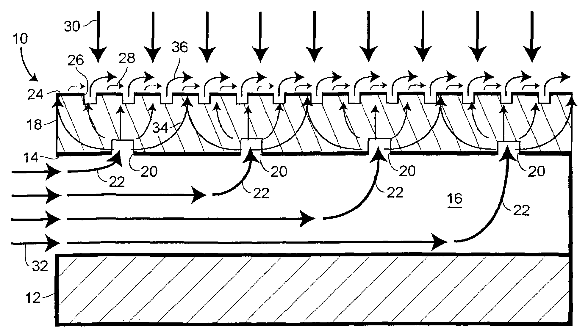
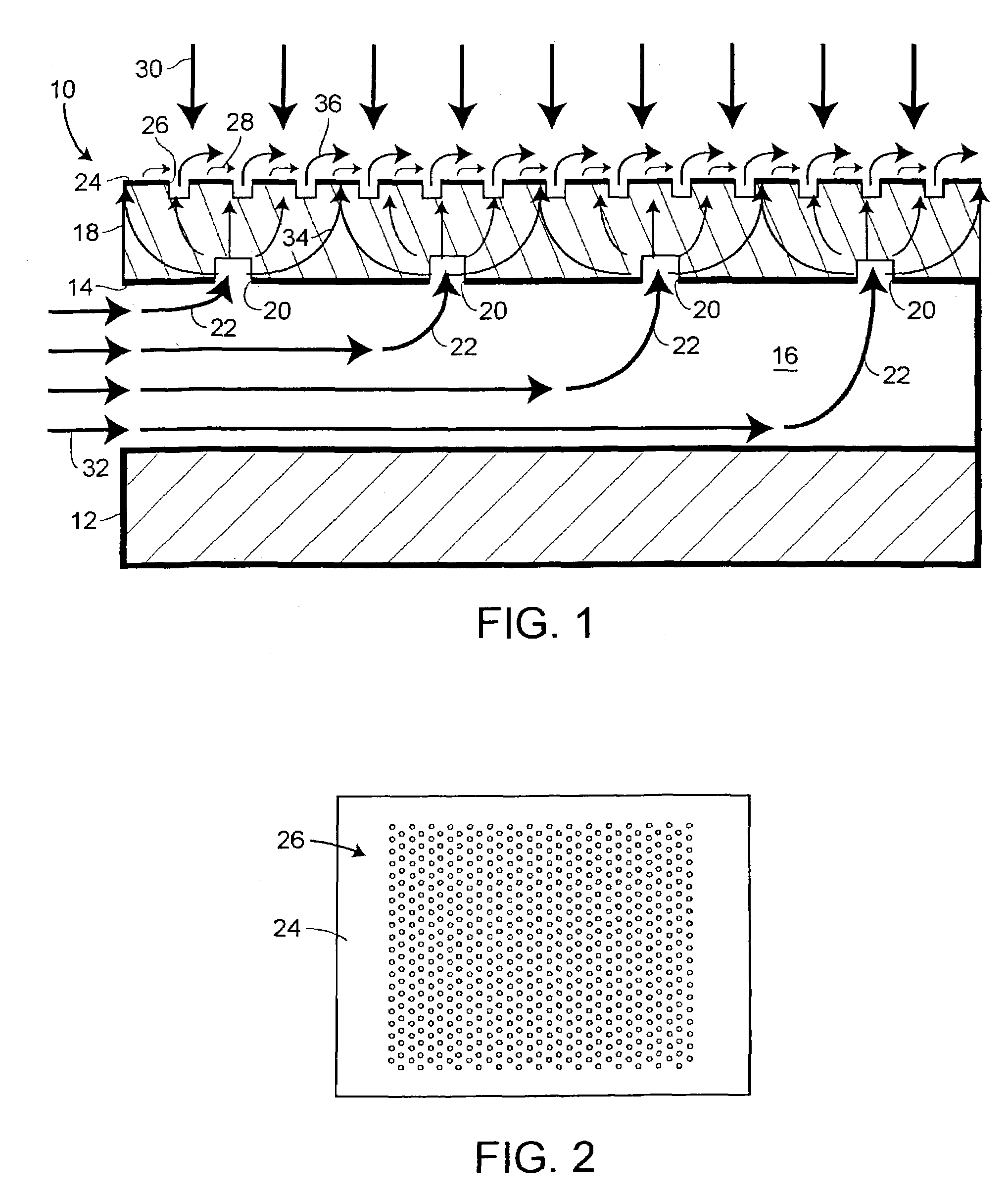
[0014]With reference initially to FIG. 1, a cooling apparatus, generally indicated at 10, includes an inner structural member 12 that is combined with an outer structural wall 14, forming a structural cooling air plenum 16 therebetween. The inner structural member 12 and the outer structural wall 14 may be formed from a metallic material, such as, titanium. A porous layer 18 may be adhesively bonded or otherwise attached to the outer structural wall 14, and entrance holes 20 may be formed in the outer structural wall 14 and may penetrate the porous layer 18 providing flow of cooling air as indicated by the bold face arrows 22 from the plenum 16 into the porous layer 18 (for example, by providing pressurized air within the plenum 16). The entrance holes 20 may, for example, have a diameter of about 2.29 mm (90 mils), a depth of up to one half the thickness of the porous layer 18, and may be spaced apart by about 6.9 mm (0.27″).

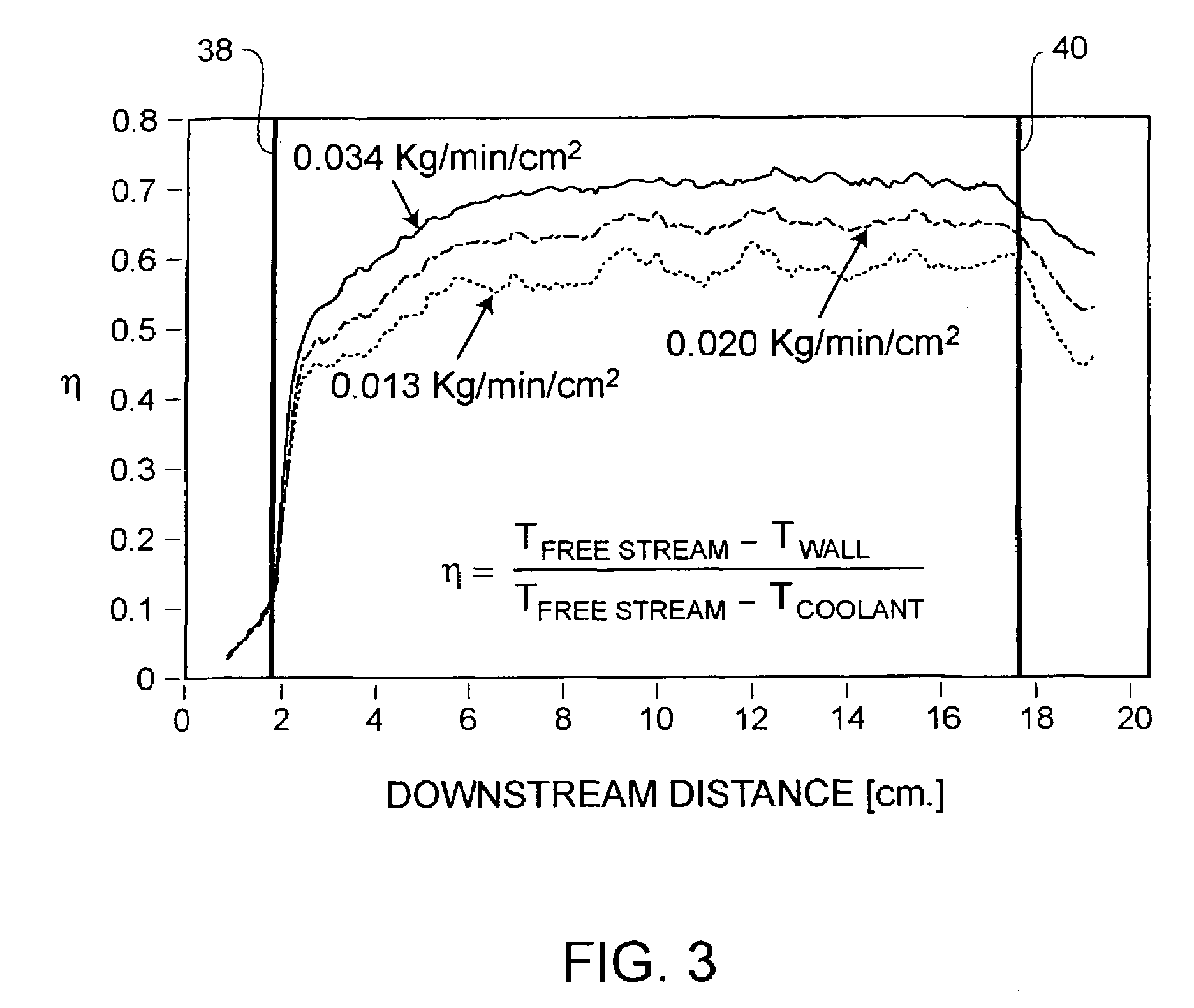
[0015]The porous layer 18 may have a void size of less th...


PUM

PropertyMeasurementUnit
thicknessaaaaaaaaaa
diameteraaaaaaaaaa
void sizeaaaaaaaaaa

Abstract

An apparatus and method for surface temperature control is provided. Surface temperature control is achieved by flowing coolant in and then out of a low strength porous layer attached to a structural plenum. A semi-permeable layer may be attached to the outer surface of the porous layer to prevent erosion of the porous layer and to facilitate surface film cooling.

Description

BACKGROUND OF THE INVENTION[0001]1. Field of the Invention[0002]This invention is generally directed to methods and apparatuses providing surface temperature control in a high heat flux environment with concurrent high velocity flow over the surface, and, more particularly, to surface temperature control methods and apparatuses traditionally involving film cooling or transpiration cooling in the aforementioned environment.[0003]2. Description of the Related Art[0004]Many engineering applications, including various components of aircraft, missiles and spacecraft, require temperature control on surfaces bounding high velocity flow while simultaneously being subjected to high incident heat flux. Conventional methods of surface temperature control under such conditions are film cooling and transpiration cooling.[0005]A typical film cooling system includes a load bearing structural plenum having a large number of small holes drilled in the outer structural wall thereof. The cooling air e...

Claims


Application Information

Patent Timeline
Patent Type & Authority Patents(United States)
IPC IPC(8): B64G1/58B64C1/38F28F13/00
CPCB64C1/38F28F13/003B64G1/58F28D2021/0078
Inventor BEHRENS, WILLIAM W.TUCKER, ANDREW R.FRENCH, JAMES E.MILLER, GAYL J.
Owner THE BOEING CO
Why Eureka
Try Eureka