Projection type video display

a projection type, video display technology, applied in the field of projection type video display, can solve the problems of increasing the size of the shading device and the inability to quickly slide the shading plate, and achieve the effect of improving the contrast of the projected video

Active Publication Date: 2006-06-06
SANYO ELECTRIC CO LTD
View PDF3 Cites 32 Cited by
  • Summary
  • Abstract
  • Description
  • Claims
  • Application Information

AI Technical Summary

Benefits of technology

[0006]In view of the foregoing circumstances, an object of the present invention is to provide a projection type video display capable of saving a space as well as rapidly shading light and easily setting light amounts at a plurality of levels.
[0008]In the above-mentioned configuration, illuminating light is shaded between the pair of fly's eye lenses, thereby making it possible to prevent the light from being incident on the light valve when the projection of the video is temporarily stopped as well as to set light amounts at a plurality of levels corresponding to the number of lenses composing the fly's eye lens, for example. Further, it is possible to save a space of a device for blocking the projection of a video as well as rapidly shading light.
[0012]In this configuration, the corresponding divided shading plates are grouped and rotated, for example, thereby making it possible to set light amounts at a plurality of levels while simplifying the rotation driving unit.
[0017]In this configuration, the number of components can be reduced.
[0019]The light at the periphery of the light source is shaded, thereby making it possible to improve the contrast of the projected video.

Problems solved by technology

Since a shading plate in a state where it does not block the projection of a video must be positioned outside an optical path, however, a sliding space for the shading plate is required outside the optical path, so that a shading device increases in size.
Further, the shading plate cannot be rapidly slid.

Method used


Image

  • Projection type video display
  • Projection type video display
  • Projection type video display

Examples


Embodiment Construction

[0034]A liquid crystal projector according to an embodiment of the present invention will be described on the basis of FIGS. 1 to 8.

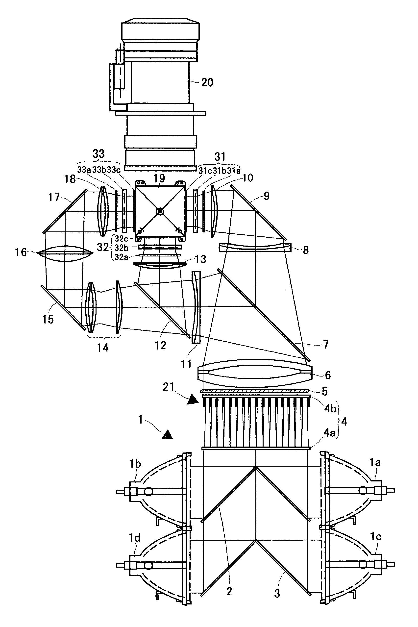
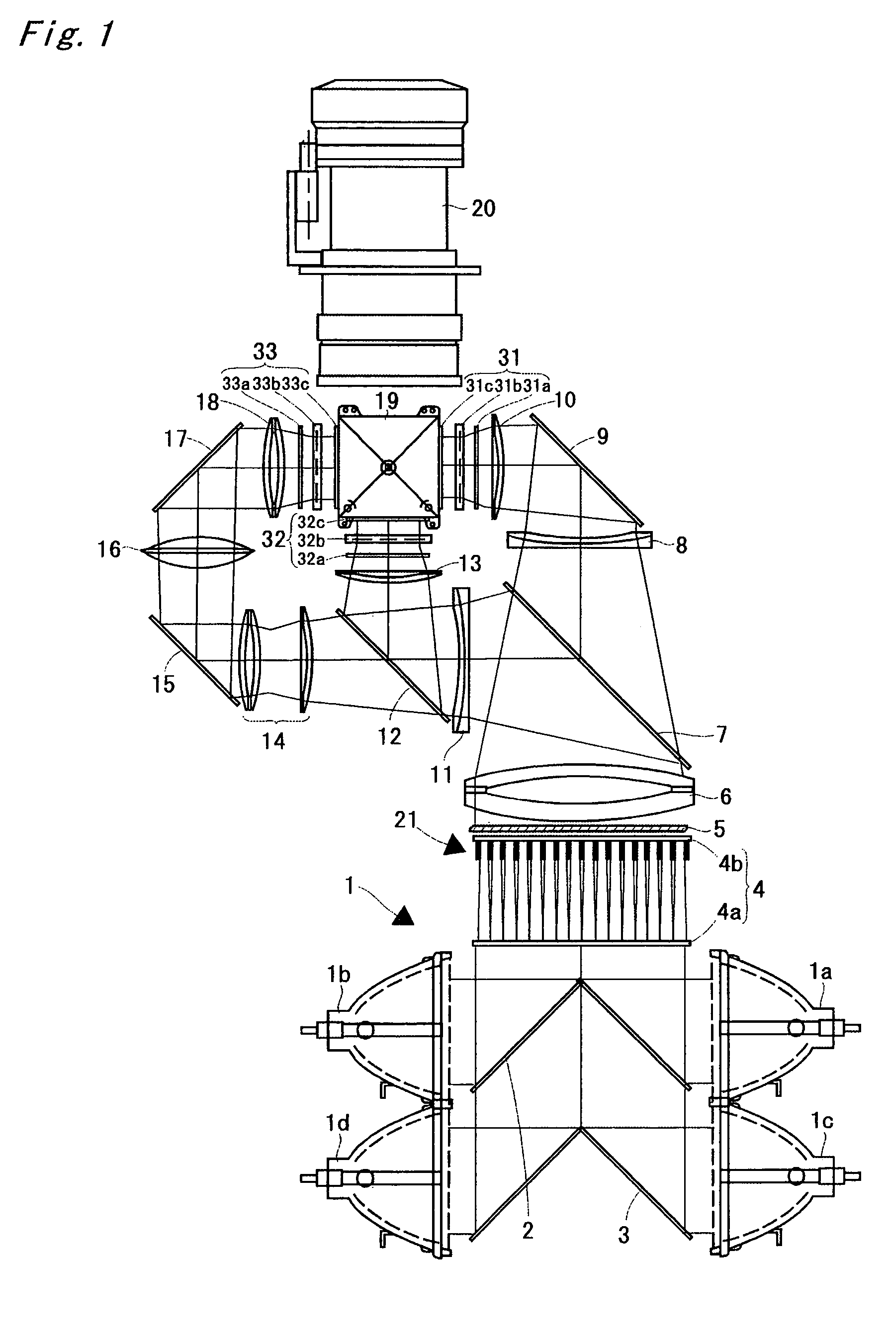
[0035]FIG. 1 is a diagram showing a four-lamp and three-panel liquid crystal projector according to an embodiment of the present invention. An illuminating device 1 comprises four light sources 1a, 1b, 1c, and 1d, a mirror 2 arranged between the light sources 1a and 1b, and a mirror 3 arranged between the light sources 1c and 1d. Each of the light sources is composed of a ultra-high pressure mercury lamp, a metal halide lamp, a xenon lamp, or the like, and its irradiated light is emitted after being changed into parallel lights by a parabolic reflector, to be introduced into an integrator lens 4.

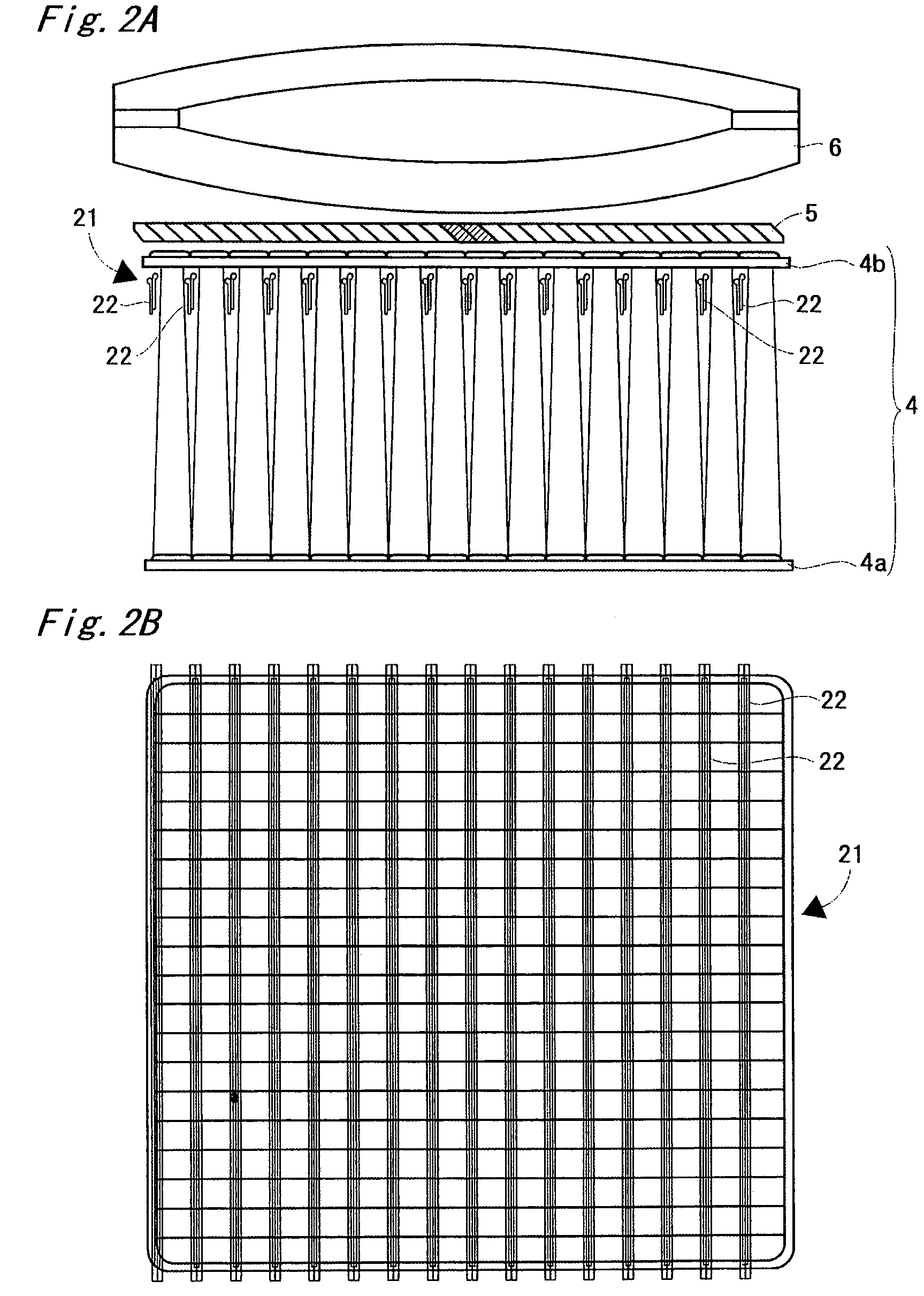
[0036]The integrator lens 4 comprises a pair of fly's eye lenses 4a and 4b. Each of the pair of lenses introduces light emitted from the illuminating device 1 into the whole surface of a liquid crystal light valve, described later, to average partial non-uniform...


PUM

PropertyMeasurementUnit
lengthaaaaaaaaaa
widthaaaaaaaaaa
heightaaaaaaaaaa

Abstract

A shutter device comprises a plurality of shutters. Each of the shutters is provided at a position in the vicinity of a fly's eye lens positioned on the side of a polarization conversion system (one of fly's eye lenses in an integrator lens) and not preventing the passage of effective illuminating light. Each of the shutters is constructed as a first shutter or a second shutter. The first shutter is constructed so as to block an upper one-third region and a lower one-third region of the fly's eye lens, and the second shutter is constructed so as to block an intermediate one-third region of the fly's eye lens

Description

BACKGROUND OF THE INVENTION[0001]1. Field of the Invention[0002]The present invention relates to a projection type video display such as a liquid crystal projector.[0003]2. Description of the Background Art[0004]As a method of utilizing a liquid crystal projector, a video signal outputted from a personal computer is received, to project a video. That is, when a person who makes a presentation operates a personal computer to display a video which he or she desires to make participants see on a display of the personal computer, the same video as the displayed video is enlarged and projected on a screen by a liquid crystal projector, so that all the participants can see the video. On the other hand, the person who makes a presentation may not, in some cases, desire a video which appears during an operation to be viewed by the participants. In order to cope with such a request, a liquid crystal projector in which a shading plate for temporarily blocking the projection of the video is sl...

Claims


Application Information

Patent Timeline
Patent Type & Authority Patents(United States)
IPC IPC(8): G03B21/14F21V17/02G02F1/1335G03B21/20G02F1/13G02B27/14G02F1/13357G03B21/00H04N5/74
CPCG02B27/1046G02B27/145H04N9/315H04N9/3141G02B27/149
Inventor KOBA, HIROKI
Owner SANYO ELECTRIC CO LTD
Why Eureka
Try Eureka