Method of inspecting magnetic recording medium based on contact duration time

a magnetic recording medium and contact duration technology, applied in the direction of maintaining the alignment of the head carrier, mechanical roughness/irregularity measurements, instruments, etc., can solve the problems of reducing the height of the magnetic head, limiting the number of disks provided in the magnetic disk apparatus, and not being able to meet the demand for increasing the recording capacity

Inactive Publication Date: 2006-06-06
SHOWA DENKO KK
View PDF10 Cites 3 Cited by
  • Summary
  • Abstract
  • Description
  • Claims
  • Application Information

AI Technical Summary

Benefits of technology

[0042]When the contact detection sensor outputs a voltage output signal, the predetermined reference voltage for the output signal level is lower than the reference voltage used in the conventional inspection method and is also lower than the output signal level supplied from the contact detection sensor in the case that the glide inspection head comes in contact with a small protrusion. Therefore the predetermined reference voltage is close to the noise level included in the output signal. However, according to the present invention, the output sig...

Problems solved by technology

However, the number of disks provided in the magnetic disk apparatus is limited because available space in the magnetic disk apparatus is limited.
Therefore, it is not possible to meet a demand for increasing the recording capacity only by means of increasing the number of disks.
When the flying height of the magnetic head is reduced, a problem with protrusions on the magnetic recording medium appears.
In the magnetic disk apparatus, the head crash means that the data write/read magnetic head comes in contact many times with relatively large protrusions on the surface of the magnetic disk and damage to the surface of the magnetic disk is expanded greatly from the protrusions, and thereby a read data error is caused, or that dust produced by the damage to the surface of the magnetic disk adheres to the flying surface of the magnetic head and therefore the stability of the flying head is lost thereby causing read data errors.
These defective magnetic disks are returned for a reworking process of the surface of the magnetic disk or disposed of, and such defective disks are never integrated into the magnetic disk apparatuses.
If the defective disk is integrated into the magnetic disk apparatus, the defective disk may cause a head crash.
However, when the device ...

Method used


Image

  • Method of inspecting magnetic recording medium based on contact duration time
  • Method of inspecting magnetic recording medium based on contact duration time
  • Method of inspecting magnetic recording medium based on contact duration time

Examples


first embodiment

[0077][The First Embodiment]

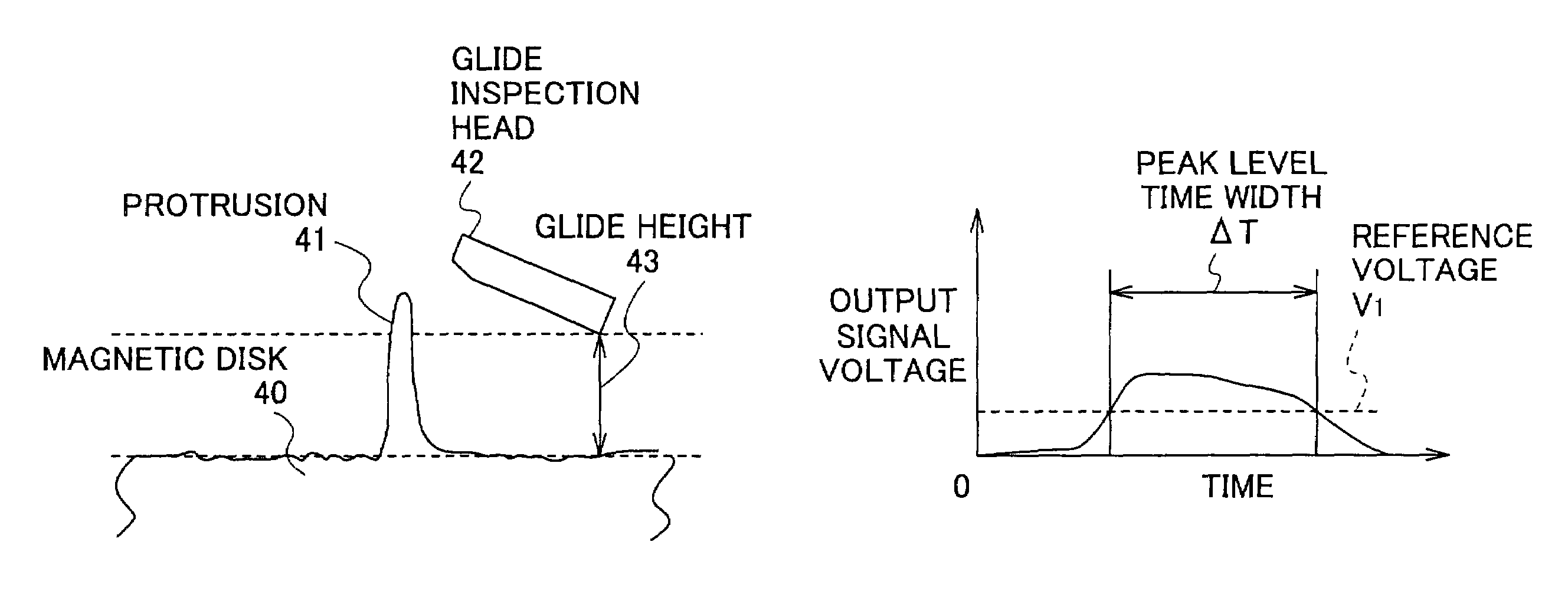
[0078]In this first embodiment, the contact duration time is used as a criterion to detect protrusions that constitute defects. The contact duration time is defined by the duration time that the output signal from the contact detection sensor has a level (voltage) greater than a reference voltage.

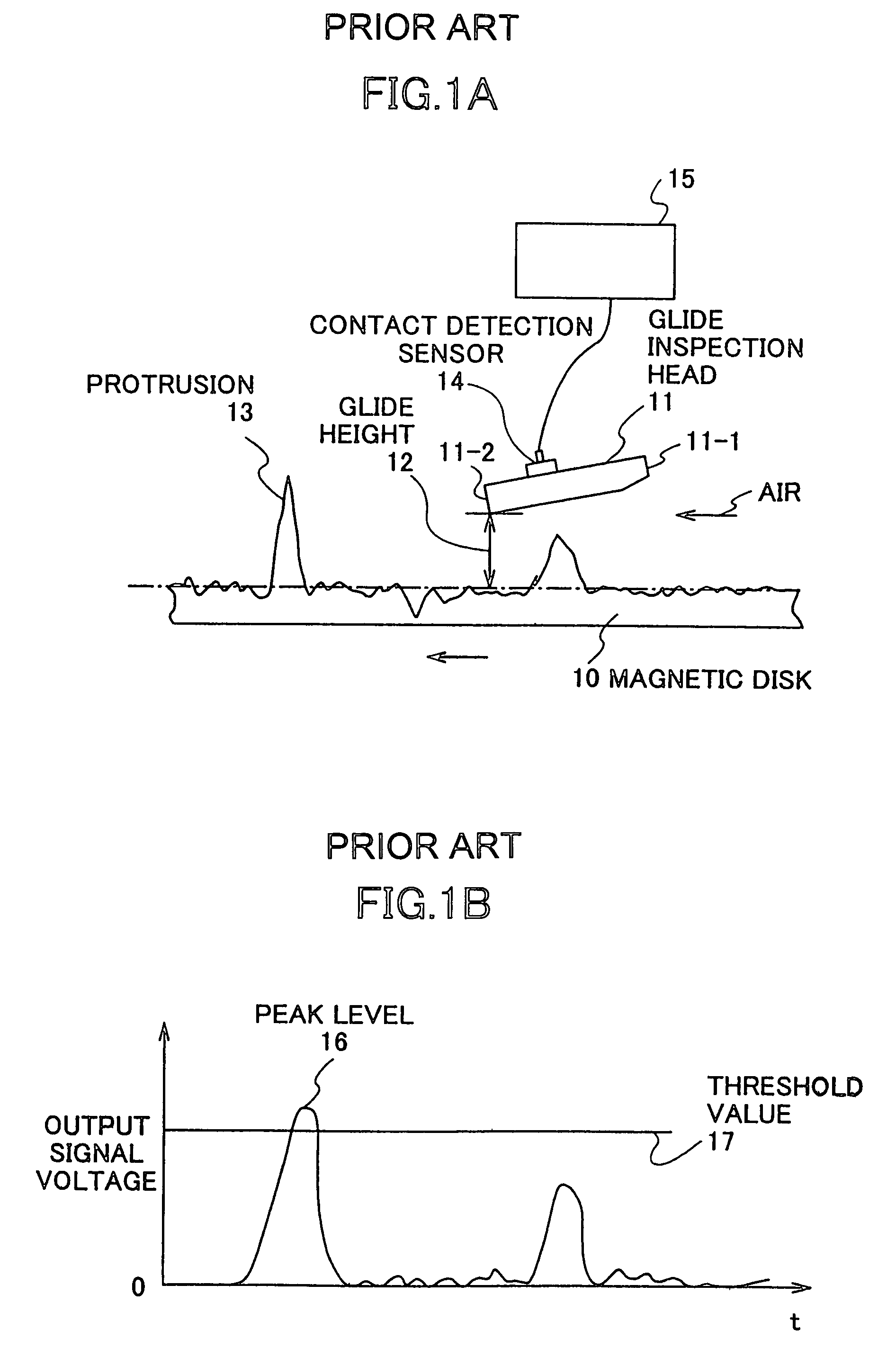
[0079]FIG. 8 shows a glide inspection apparatus 100 to explain the inspection method for the magnetic disks of the embodiments of the present invention. A magnetic disk 101 is fixed by a clamp 103 and rotated by a spindle motor 102 in the direction shown by an arrow at a predetermined number of revolutions per minute. A glide inspection head 104 is attached at the top of a suspension 106 supported by a head support arm 105. The glide inspection head 104 accesses the upper surface of the magnetic disk 101 and conducts the glide inspection over the whole area of the upper surface of the magnetic disk 101 while the glide inspection head 104 is kept opposing the magn...

second embodiment

[0086][The Second Embodiment]

[0087]In this second embodiment, the peak level of the output signal from the contact detection sensor is also used as a criterion to detect protrusions that constitute defects as well as the contact duration time ΔT.

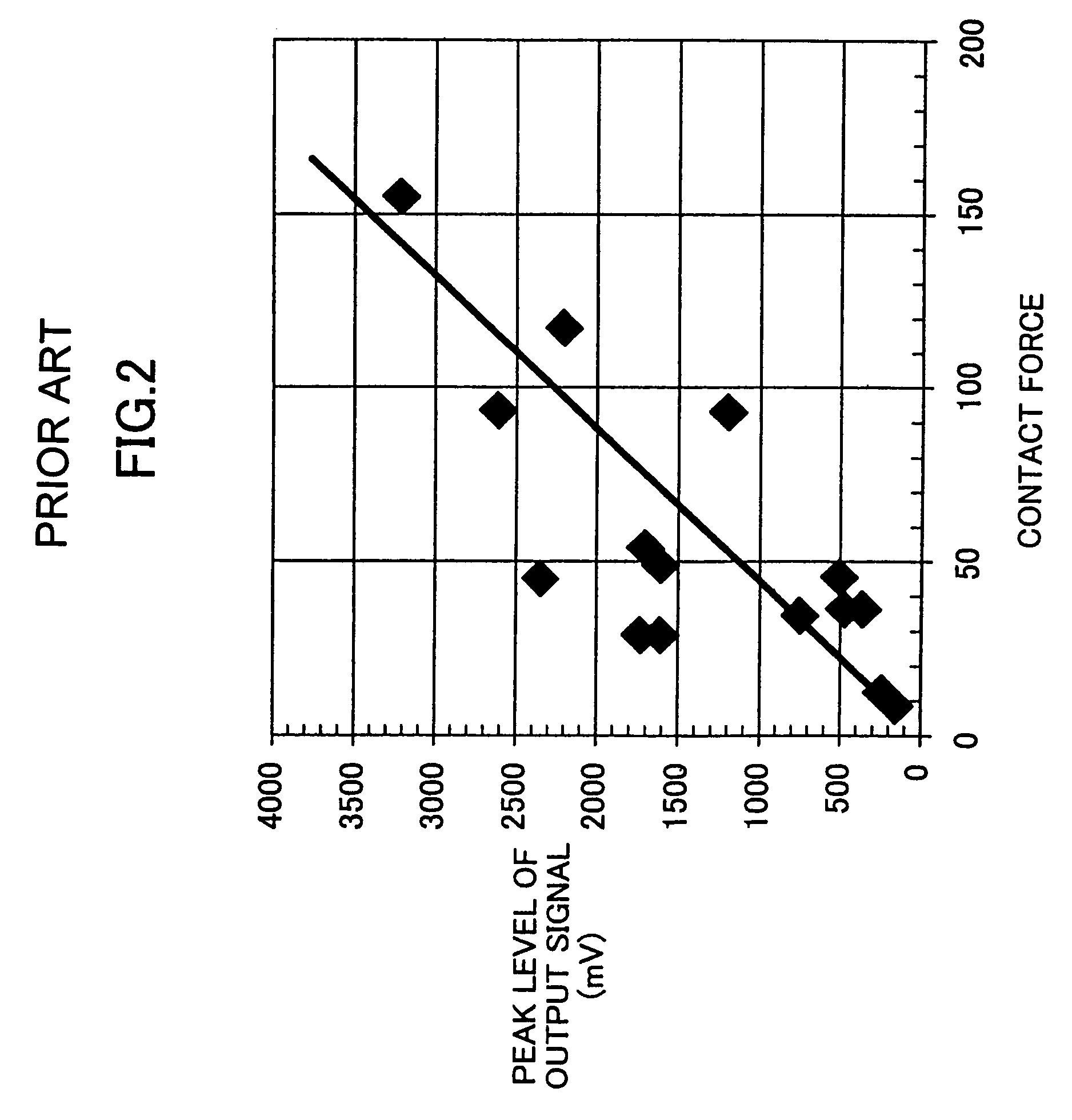
[0088]The same as described in the first embodiment, the output signal from the piezoelectric device 114 is amplified by the amplifier 107 and the amplified signal is supplied to the signal analysis apparatus 108. The signal analysis apparatus 108 detects the protrusions that constitute the defects. FIG. 11 shows the relationship between the output signal of the piezoelectric device 114 and the threshold values. As shown in FIG. 11, two threshold values are provided for the output signal. One threshold value is the threshold value ΔTTH for the duration time ΔT. Another threshold value is the threshold value VTH for the peak level Vp of the output signal. The threshold value ΔTTH is set to a value of 100 μsec and the threshold value VTH is se...

third embodiment

[0090][The Third Embodiment]

[0091]In the third embodiment, a linear sum of the weighted value of the peak level of the output signal from the contact detection sensor and the contact duration time ΔT as described in the second embodiment is used as a criterion to detect protrusions that constitute defects. The same measurements as the second embodiment were conducted. A calculated value X is equal to ΔT×20+Vp (X=ΔT×20+Vp), where ΔT (μsec) is the contact duration time and Vp (mV) is the peak level. The threshold value XTH for the calculated value X is set to 3000. When the calculated value X exceeds the threshold value XTH equaling 3000, the corresponding protrusion is detected as a defect.

[0092]The results of the inspection are shown in FIG. 12. FIG. 12 shows results of the glide inspection of the third embodiment of the present invention.

[0093]As shown in FIG. 12, the protrusions A and C are detected as defects. The protrusion B is not detected. As described above, the protrusion B...


PUM


Abstract

A magnetic recording medium inspection method detects small protrusions that constitute defects on the surface of a magnetic recording medium. The method includes flying a glide inspection head at a predetermined height over the surface of the moving magnetic recording medium; detecting a contact duration time during which the glide head is in contact with a protrusion on the surface of the magnetic recording medium using a contact detection sensor attached to the glide inspection head; and determining the small protrusion based on the contact duration time.

Description

BACKGROUND OF THE INVENTION[0001]1. Field of the Invention[0002]The present invention generally relates to an inspection method for a magnetic recording medium provided in a magnetic recording apparatus that is used as an external storage device of a computer.[0003]2. Description of the Related Art[0004]Recently, information technology has been advancing and thereby it is required to increase storage capacity of magnetic recording apparatuses. In order to increase storage capacity of the magnetic recording apparatus, for example, the number of magnetic disks can be increased in a magnetic disk apparatus which is one of the magnetic recording apparatuses. However, the number of disks provided in the magnetic disk apparatus is limited because available space in the magnetic disk apparatus is limited. Therefore, it is not possible to meet a demand for increasing the recording capacity only by means of increasing the number of disks.[0005]Therefore, it is required to increase the record...

Claims


Application Information

Patent Timeline
IPC IPC(8): G01R33/12G11B5/00G11B5/84G11B5/012G11B5/60
CPCG01R33/1207G11B5/00G11B5/6005G11B2005/001G11B5/012
Inventor YOKOHATA, TORUIMAMURA, TAKAHIROFUJITA, TOSHIYAOCHIAI, YOJIROOZEKI, MASAHIROSATAKE, NAOKI
Owner SHOWA DENKO KK
Why Eureka
Try Eureka