

Power module and production method thereof
a technology of power modules and production methods, applied in the direction of supporting structure mounting, electrical apparatus construction details, non-metallic protective coating applications, etc., can solve the problems of high cost of molds for heat sinks with complicated shapes, difficult to bring all components into uniform coherence with the heat sink, etc., to achieve high reliability, high reliability, and efficient heat taking
- Summary
- Abstract
- Description
- Claims
- Application Information
AI Technical Summary
Benefits of technology
Problems solved by technology
Method used
Image

Examples
first embodiment
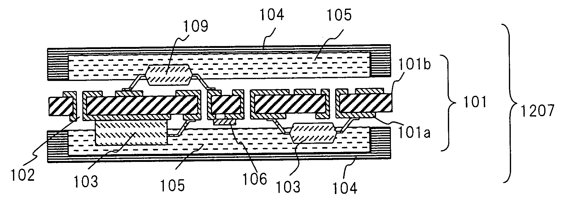
[0065]A power module in accordance with a first embodiment will be described referring to FIG. 1.
[0066]FIG. 1 is a sectional view showing configuration of the power module in accordance with the first embodiment of the present invention. In FIG. 1, a reference numeral 107 denotes the power module in accordance with the first embodiment of the present invention. The power module 107 comprises a multi-layer board 101 with a through hole 102, electronic components requiring heat dissipation 103 (each having an arbitrary different height), a heat sink 104, a high thermal conductive member 105 and electronic components 106.
[0067]The power module of this embodiment consists of three members including the multi-layer board 101, the high thermal conductive member 105 and the heat sink 104. The electronic components 103 and 106 are mounted to an insulating board 101b of the multi-layer board 101. The electronic components requiring heat dissipation 103 such as an electric power conversion ci...
second embodiment
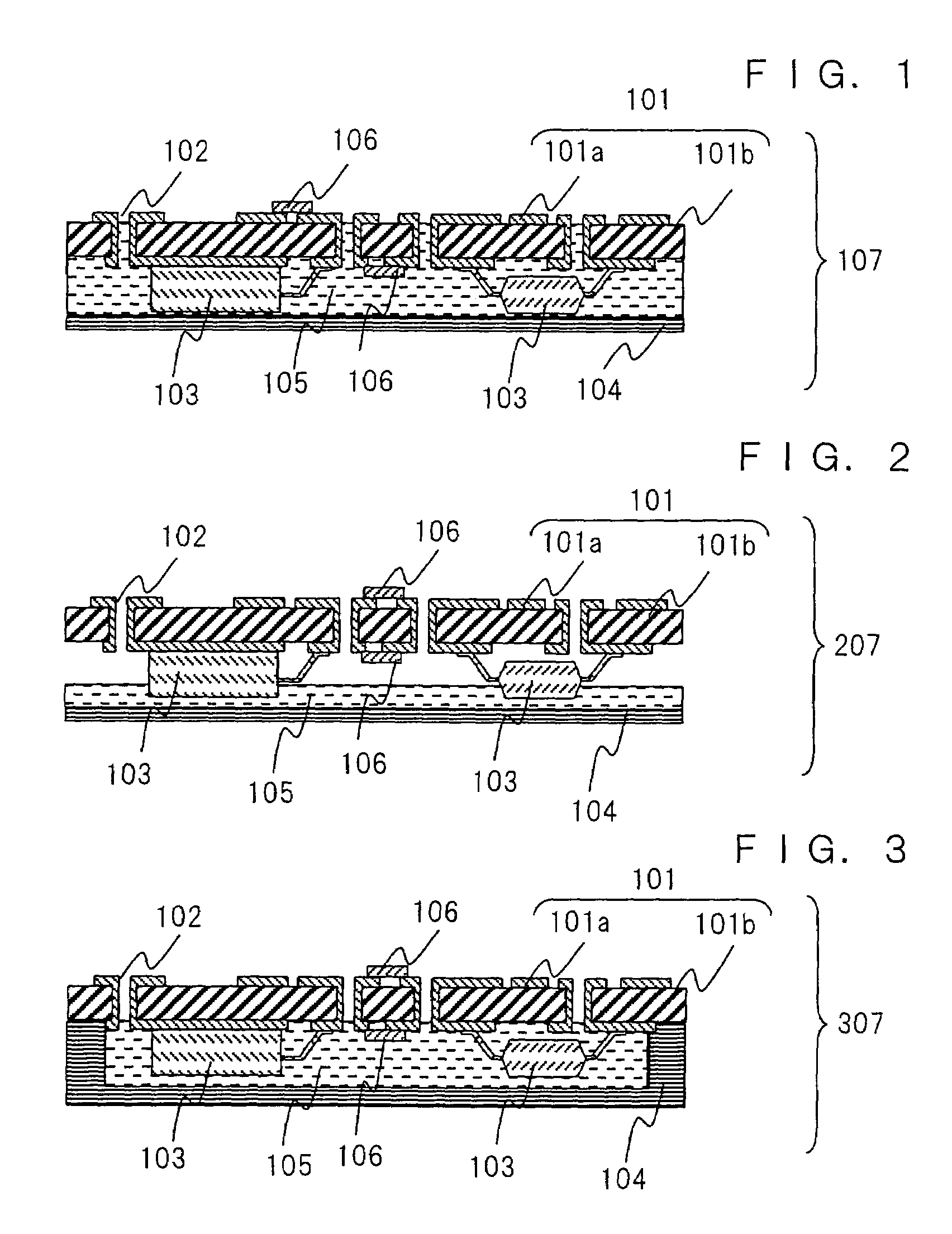
[0080]A power module in accordance with a second embodiment will be described referring to FIG. 2.
[0081]FIG. 2 is a sectional view showing configuration of the power module in accordance with the second embodiment of the present invention. In FIG. 2, a reference numeral 207 denotes the power module in accordance with the second embodiment. The power module 207 of this embodiment comprises the multi-layer board 101 with the through hole 102, the electronic components requiring heat dissipation 103 (each having an arbitrary different height), the heat sink 104, the high thermal conductive member 105 and the electronic components 106.
[0082]The power module of the second embodiment is different from the power module of the first embodiment in that the high thermal conductive member 105 is formed so as to embed only a part of the electronic components 103 therein, thereby to provide space between the high thermal conductive member 105 and the surface of the multi-layer board 101. The hig...
third embodiment
[0087]A power module in accordance with a third embodiment will be described referring to FIG. 3.
[0088]FIG. 3 is a sectional view showing configuration of the power module in accordance with the third embodiment of the present invention. In FIG. 3, a reference numeral 307 denotes the power module in accordance with this embodiment. The power module 307 of the third embodiment comprises the multi-layer board 101 with the through hole 102, the electronic components requiring heat dissipation 103 (each having an arbitrary different height), the heat sink 104, the high thermal conductive member 105 and the electronic components 106.
[0089]The power module of this embodiment is different from that of the first embodiment in that the heat sink 104 is of recessed shape, and the high thermal conductive member 105 that envelops (embeds) the electronic component requiring heat dissipation 103 therein is enclosed with the heat sink 104. With such configuration, heat generated from the electroni...
PUM
 Abstract
Description
Claims
Application Information