Superconducting filter apparatus and wireless receiving amplifier having an abnormality discriminating circuit
a filter apparatus and filter circuit technology, applied in the direction of superconducting magnets/coils, magnetic bodies, waveguides, etc., can solve the problems of communication failure, possible mechanical malfunction, and increase in pass band loss, and achieve the effect of reliably discriminating abnormalities of low-noise amplifiers
- Summary
- Abstract
- Description
- Claims
- Application Information
AI Technical Summary
Benefits of technology
Problems solved by technology
Method used
Image
Examples
first embodiment
(A) First Embodiment
(a) Overall Configuration
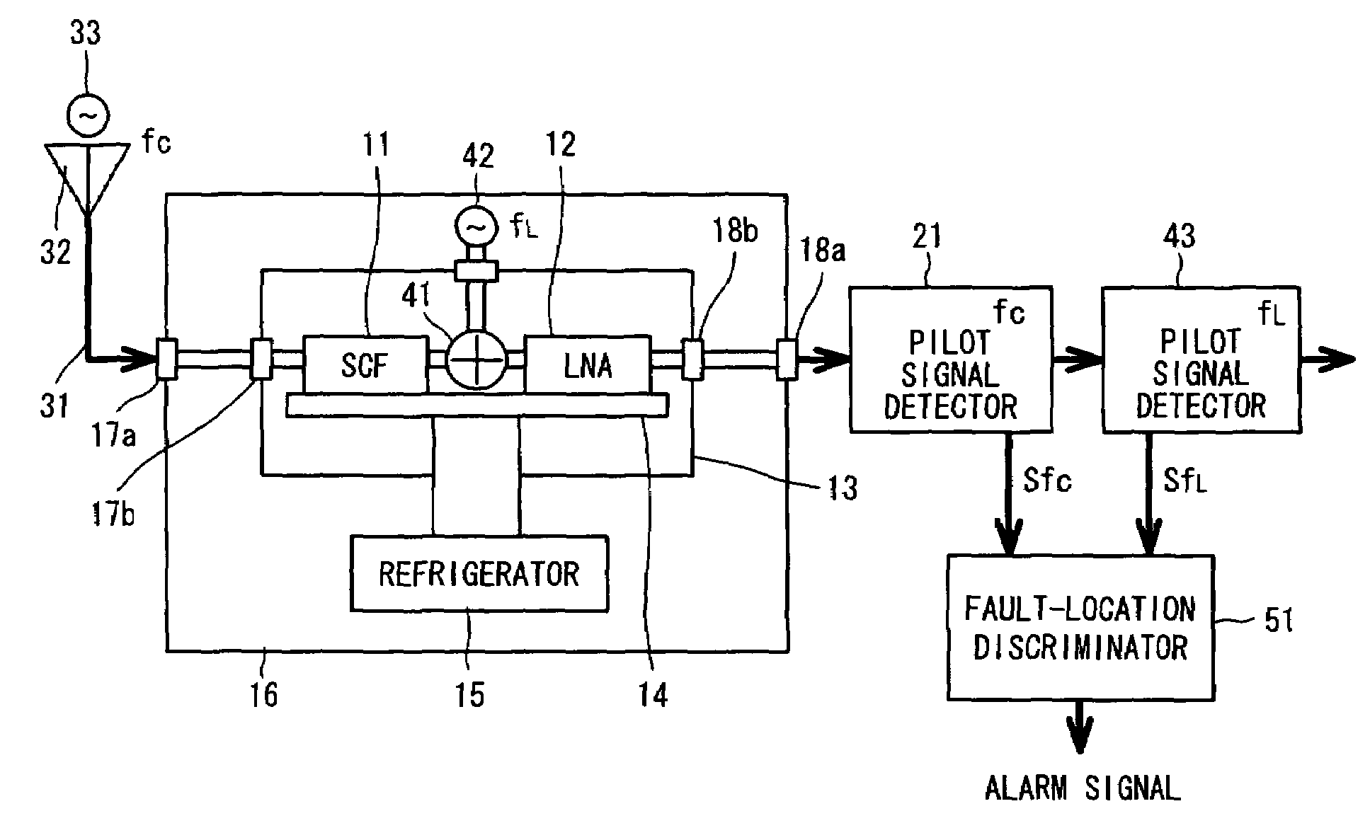
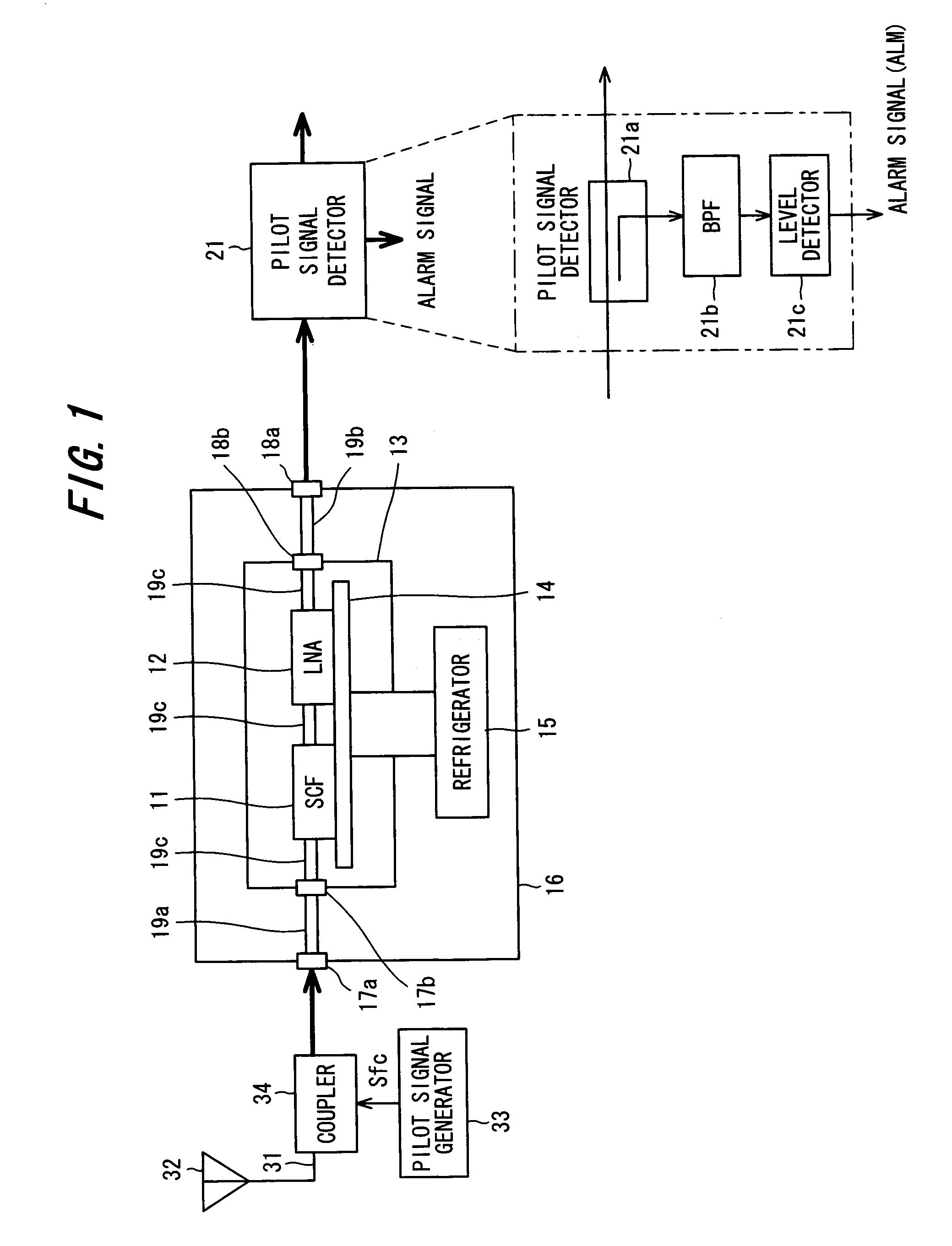
[0043]FIG. 1 is a diagram showing the structure of a wireless receiving amplifier according to the present invention. A superconducting filter (SCF) 11 and low-noise amplifier (LNA) 12 are secured to a cold head 14 and accommodated within a vacuum vessel 13. The cold head 14 is cooled by a refrigerator 15. The superconducting filter 11 and low-noise amplifier 12 are cooled by the refrigerator 15 via the cold head 14 and operate at Tc=70 K. The vacuum vessel 13 and refrigerator 15 are disposed in a case 16 in such a manner that outdoor installation is possible. Terminals 17a, 17b and 18a, 18b provided on the case 16 and vacuum vessel 13 are connected by coaxial cables 19a, 19b, respectively, and terminal 17b, superconducting filter 11, low-noise amplifier 12 and terminal 18b are connected by a coaxial cable 19c.
[0044]A receive antenna 32 is connected to input terminal 17a of the case 16 via an antenna feeder 31, and a signal that has been...
second embodiment
(B) Second Embodiment
[0056]FIG. 6 is a diagram showing the structure of a second embodiment of the present invention. This embodiment has a preferable arrangement for inserting a pilot signal into the signal received by the antenna. Components identical with those of the first embodiment in FIG. 1 are designated by like reference characters.
[0057]The pilot signal can be impressed upon the antenna receive signal using a coupler or the like, as in the first embodiment. However, loss at the output stage of the low-noise amplifier 12 increases, the noise figure (NF) increases and the advantage of cooling the low-noise amplifier 12 cannot be fully exploited. Accordingly, the pilot signal generator 33 is placed in the vicinity of the receive antenna 32, as shown in FIG. 6. The pilot signal generator 33 has an oscillator 33a for generating a pilot signal having the frequency fc outside the pass band of the superconducting filter 11, and a directional antenna 33b for radiating the pilot sig...
third embodiment
(C) Third Embodiment
[0058]FIG. 7 is a diagram showing the structure of a third embodiment of the present invention. This arrangement is the same as that of the second embodiment in FIG. 6 except for the fact that an isolator 35 is provided between the receive antenna 32 and the input terminal 17a of the case 16. Identical components are designated by like reference characters.
[0059]In a case where the refrigerator 15 is operating normally, the pilot signal outside the pass band of the superconducting filter 11 is almost totally reflected by the filter portion and the reflected pilot signal radiates from the antenna 32. In a case where the antenna 32 possesses directivity and has gain, the reflected signal is radiated with a higher signal level at this time and may constitute interference with respect to other communication channels. Accordingly, in the third embodiment, the isolator 35 is inserted into the antenna feeder 31 to isolate the pilot signal that is reflected from the supe...
PUM
| Property | Measurement | Unit |
|---|---|---|
| temperature | aaaaa | aaaaa |
| temperature Tc | aaaaa | aaaaa |
| thickness | aaaaa | aaaaa |
Abstract
Description
Claims
Application Information
 - R&D
- Intellectual Property
- Life Sciences
- Materials
- Tech Scout
- Unparalleled Data Quality
- Higher Quality Content
- 60% Fewer Hallucinations
Browse by: Latest US Patents, China's latest patents, Technical Efficacy Thesaurus, Application Domain, Technology Topic, Popular Technical Reports.
© 2025 PatSnap. All rights reserved.Legal|Privacy policy|Modern Slavery Act Transparency Statement|Sitemap|About US| Contact US: help@patsnap.com


