Control method for high-pressure hydrogen vehicle fueling station dispensers

a technology of hydrogen fueling station and control method, which is applied in the direction of container discharging method, liquid handling, packaged goods type, etc., can solve the problems of increasing the manufacturing cost and vehicle weight of the station, severe underfilling, and reducing the density of hydrogen gas, so as to achieve the effect of reducing dispenser and vehicle cos

Inactive Publication Date: 2006-06-13
GAS TECH INST
View PDF7 Cites 67 Cited by
  • Summary
  • Abstract
  • Description
  • Claims
  • Application Information

AI Technical Summary

Benefits of technology

[0011]Accordingly, it is one object of this invention to provide a method and system for fast filling of vehicle hydrogen storage vessels which reduces the potential for underfilling of the vessel.
[0012]It is another object of this invention to provide a method and system for fast filling of vehicle hydrogen storage vessels which compensates for the vessel gas temperature rise during charging.
[0013]It is yet another object of this invention to provide a method and system for fast filling of vehicle hydrogen storage vessels which compensates for initial vessel and filling station gas supply conditions.
[0015]The crux of this invention is an algorithm used to control the fill process, which interacts with the hydrogen dispensing apparatus to determine the vehicle hydrogen storage vessel capacity. In addition, there is no requirement of on-board vehicle instrumentation, or interaction either by means of vehicle installed bar coding or other electronic or radio means with the hydrogen dispenser, thereby contributing to lower dispenser and vehicle costs.

Problems solved by technology

This underfilling represents a serious marketing obstacle to be overcome by the hydrogen supply industry, without resorting to unnecessarily high fueling station gas and vehicle storage pressures, which can increase station manufacturing costs and vehicle weights.
This, in turn, decreases the density of the hydrogen gas, causing severe underfilling, if not compensated for in the fill algorithm, for the same transient storage gas pressure.
Depending on the dispenser, this level of vessel cut-off pressure may have some dependency on ambient or station gas conditions, but no known existing hydrogen dispensers compensate for the vessel gas temperature rise during charging as well as for initial vessel and station gas supply conditions.
The temperature that the vehicle hydrogen vessel gas reaches at the end of the dynamic charging process is difficult to accurately estimate or measure and utilize in a dispenser fill and control methodology.
Testing has shown this temperature to be non-uniform at the end of the fill.

Method used


Image

  • Control method for high-pressure hydrogen vehicle fueling station dispensers
  • Control method for high-pressure hydrogen vehicle fueling station dispensers
  • Control method for high-pressure hydrogen vehicle fueling station dispensers

Examples


Embodiment Construction

[0021]We have developed a unique and dynamic model of a hydrogen fast fill process, called CHARGEH2, and have correlated the results of that model output to experimental data on actual vehicle hydrogen storage vessel fill cases, over a wide variety of supply, ambient, and vessel gas conditions. Regression equations were fitted with the results obtained from the model to permit relatively easy implementation in the software available on current microprocessors, and a hydrogen dispenser control algorithm was developed, enabling use of minimal dispenser instrumentation.

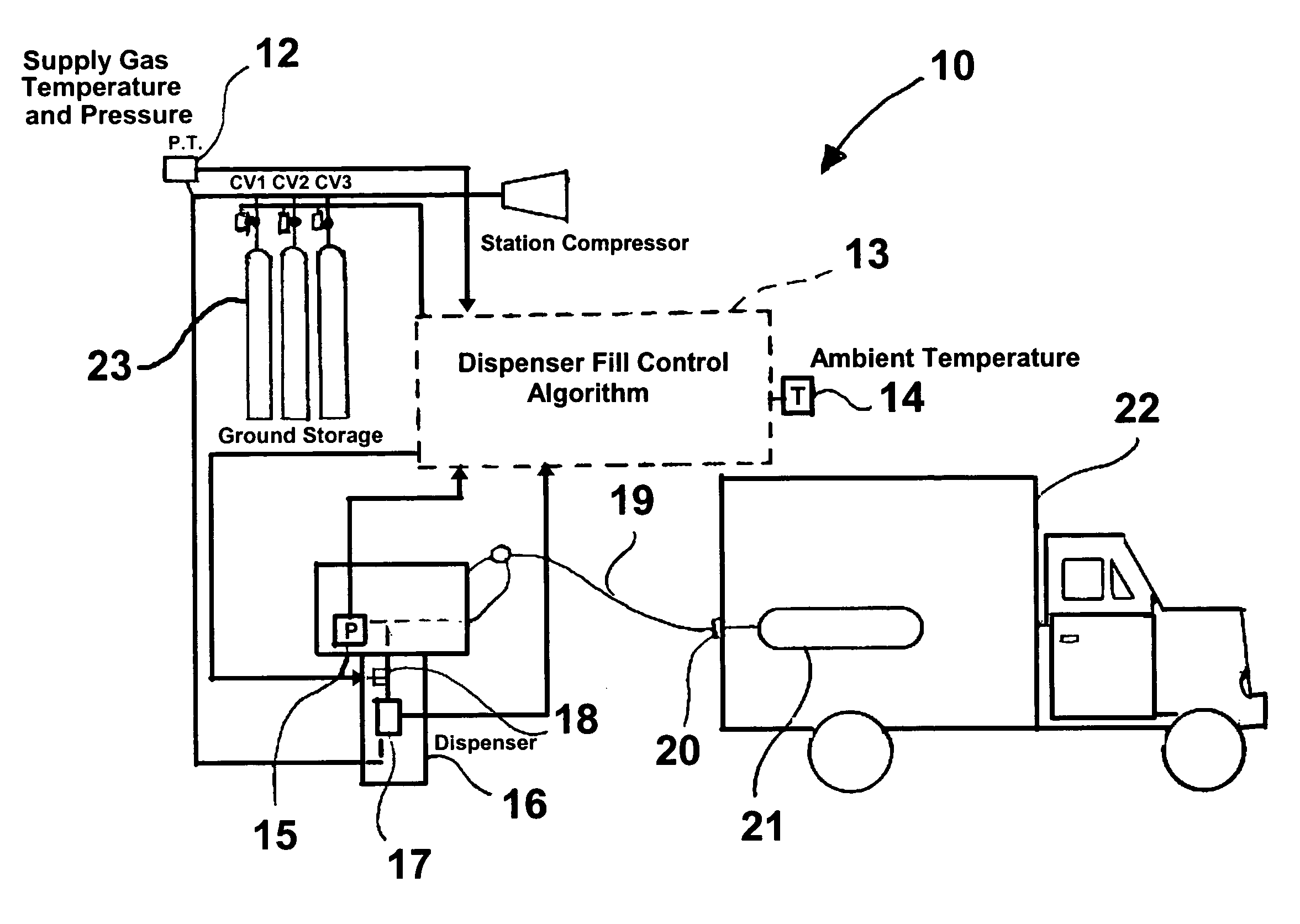
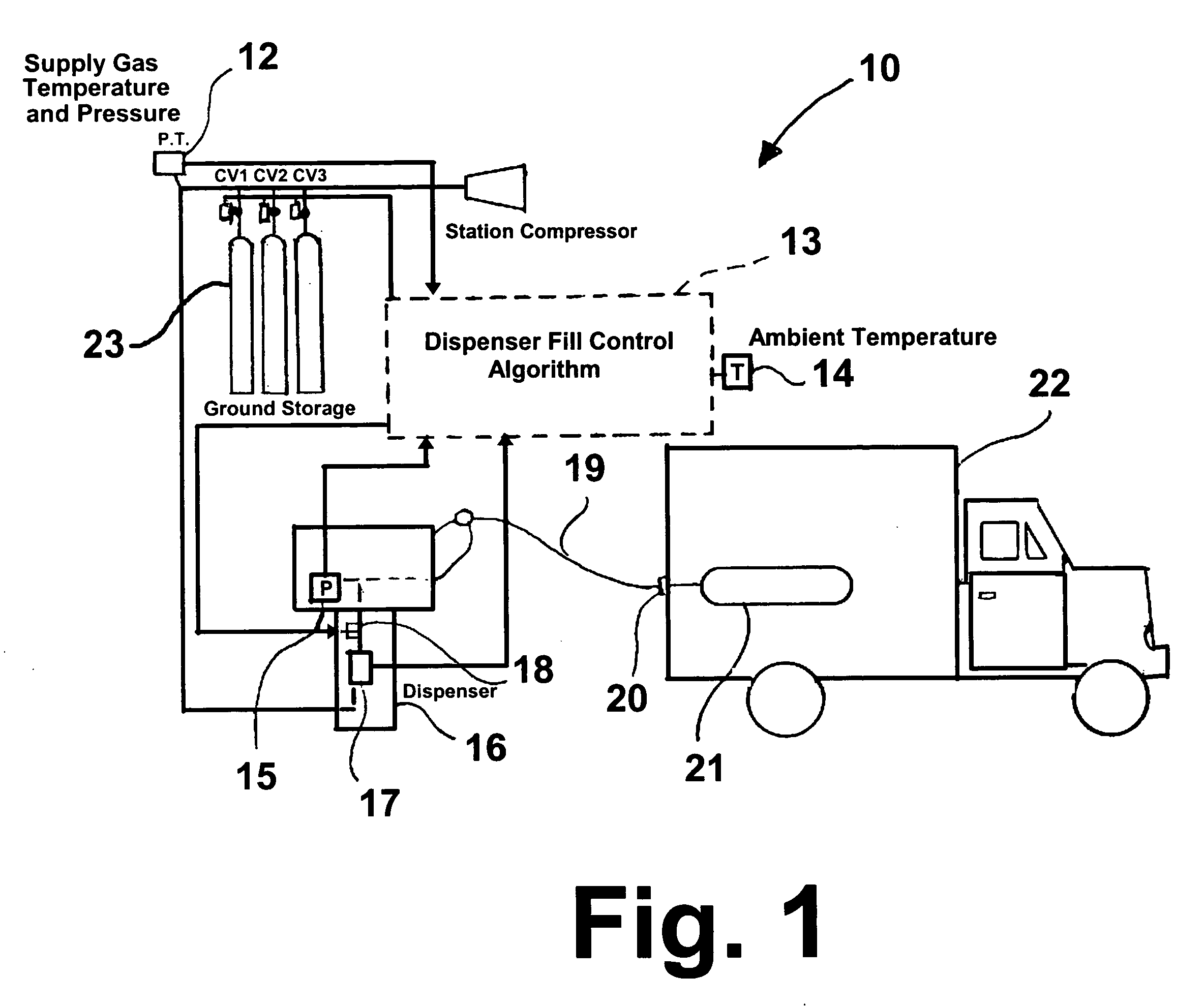
[0022]FIG. 1 shows a hydrogen gas dispenser control system 10 in accordance with one embodiment of this invention suitable for carrying out the method of this invention. The system comprises a ground storage facility comprising a multi-stage or cascade supply unit in the form of cylinders 23, each of which is equipped with a control valve labeled CV1, CV2, and CV3 for controlling the particular cascade cylinder supplying...


PUM

PropertyMeasurementUnit
temperaturesaaaaaaaaaa
gas temperatureaaaaaaaaaa

Abstract

A method for quick filling a vehicle hydrogen storage vessel with hydrogen, the key component of which is an algorithm used to control the fill process, which interacts with the hydrogen dispensing apparatus to determine the vehicle hydrogen storage vessel capacity.

Description

CROSS-REFERENCE TO RELATED APPLICATION[0001]This application claims the benefit of provisional U.S. patent application Ser. No. 60 / 543,895, filed 12 Feb. 2004.[0002]The U.S. Government has a paid-up license in this invention and the right in limited circumstances to require the patent owner to license others on reasonable terms as provided for by the terms of contract No. DE-FC36-02AL67607 awarded by the U.S. Department of Energy.BACKGROUND OF THE INVENTION[0003]1. Field of the Invention[0004]This invention relates to a method and system for fueling hydrogen-fueled vehicles including internal combustion engine and fuel cell powered vehicles. More particularly, this invention relates to a method and system for controlling high-pressure hydrogen dispensers in fast-fill fueling stations to ensure complete, safe filling of vehicle on-board hydrogen storage vessels, regardless of station hydrogen supply gas and ambient conditions.[0005]2. Description of Related Art[0006]The on-board stor...

Claims


Application Information

Patent Timeline
Patent Type & Authority Patents(United States)
IPC IPC(8): B65B31/00B65B1/04B65B1/30F17C9/02
CPCF17C9/02Y02E60/321F17C2205/0142F17C2205/0326F17C2205/0335F17C2205/035F17C2205/0376F17C2221/012F17C2223/0123F17C2223/036F17C2225/0123F17C2225/036F17C2227/043F17C2250/032F17C2250/043F17C2250/0439F17C2250/0443F17C2250/075F17C2260/025F17C2260/026F17C2265/065F17C2270/0168F17C2270/0184F17C2205/013Y02E60/32
Inventor KOUNTZ, KENNETH JOHNKRIHA, KENNETH ROBERTLISS, WILLIAM E.
Owner GAS TECH INST
Why Eureka
Try Eureka