Optical fiber bundle, light source device using the optical fiber bundle, and method for manufacturing the light source device
a technology of optical fiber bundles and light sources, applied in waveguides, lighting and heating apparatuses, instruments, etc., can solve the problems of difficult to reduce light intensity, resist light exposure, and existing light source devices that cannot perform such area definitions, so as to achieve efficient control of output light intensity distribution
- Summary
- Abstract
- Description
- Claims
- Application Information
AI Technical Summary
Benefits of technology
Problems solved by technology
Method used
Image
Examples
first embodiment
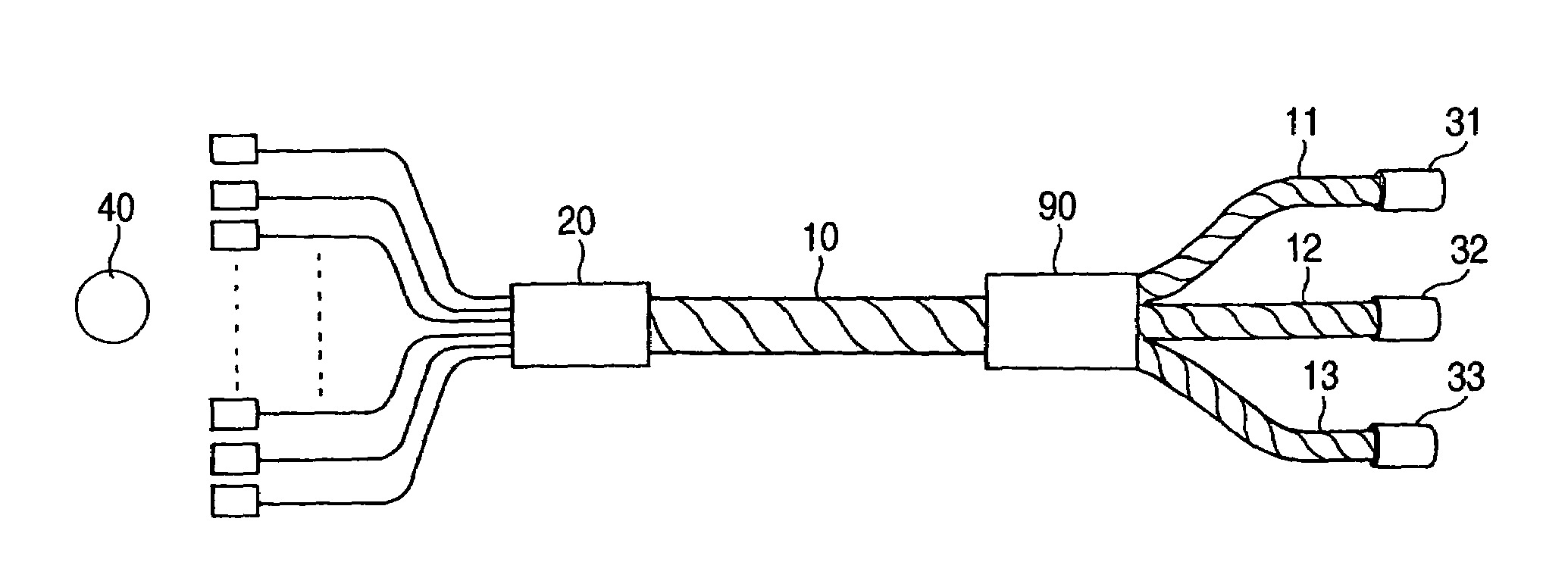
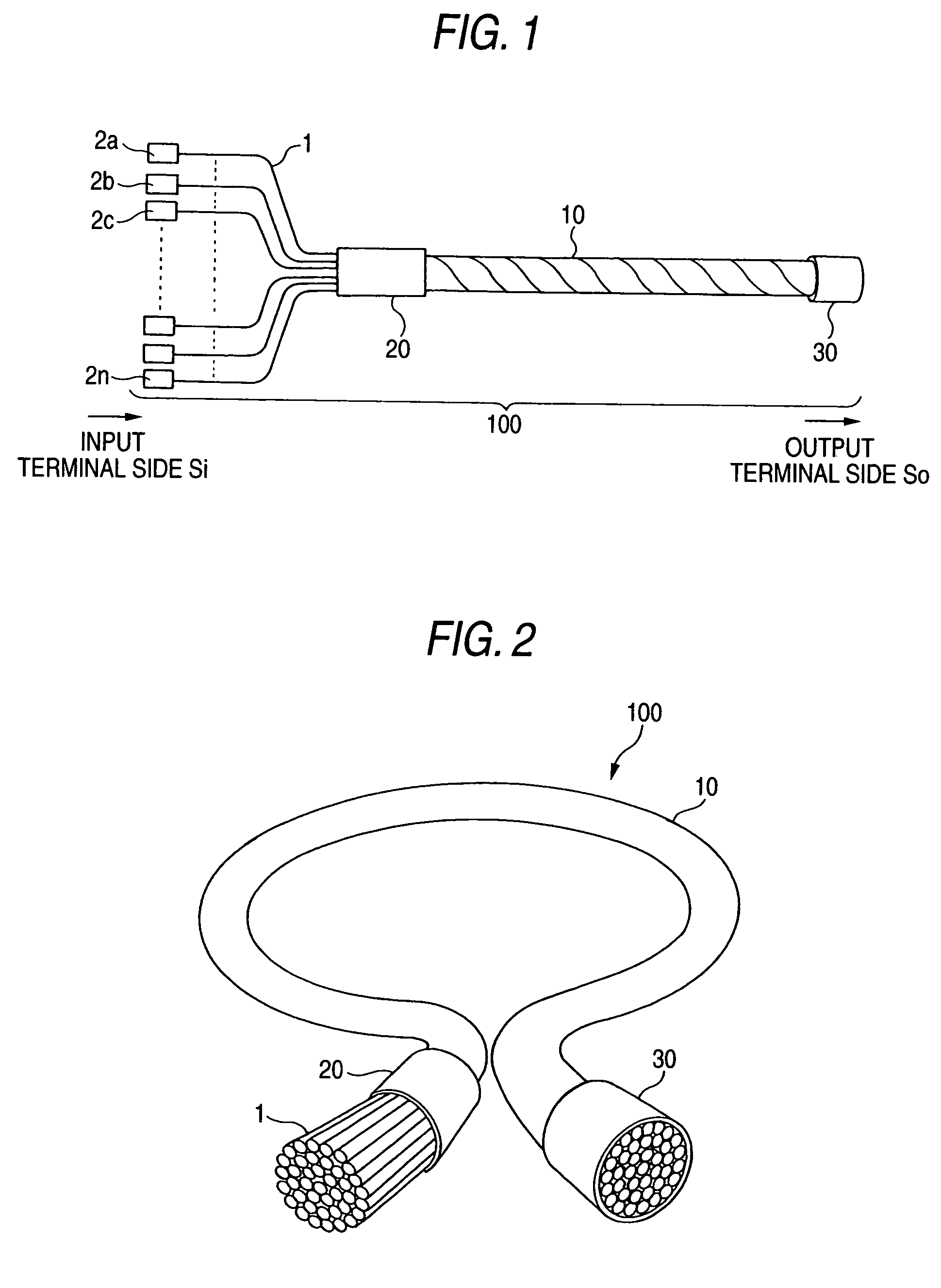
[0093]An optical fiber bundle according to a first embodiment of the invention is an optical fiber bundle 100 including 25 optical fibers 1 bundled on an input terminal side Si and on an output terminal side So as shown in its conceptual diagrams of FIGS. 1 and 2. The optical fiber bundle 100 is designed to receive light from the input terminal side Si and outputs the light to the output terminal side. The optical fiber bundle 100 has a feature in that the optical fibers 1 are divided, on the input terminal side Si, individually or into a plurality of groups in accordance with their positions on the output terminal side So that input light can be adjusted for each optical fiber or for each group.
[0094]A cap 30 is attached to the output terminal side so as to expose the optical fiber ends to the outside. The cap 30 has a function of connecting member. Each of the optical fiber ends has a mirror-finished end face. On the other hand, on the input terminal side, the optical fiber 1 are ...
second embodiment
[0103]Next, a second embodiment of the invention will be described.
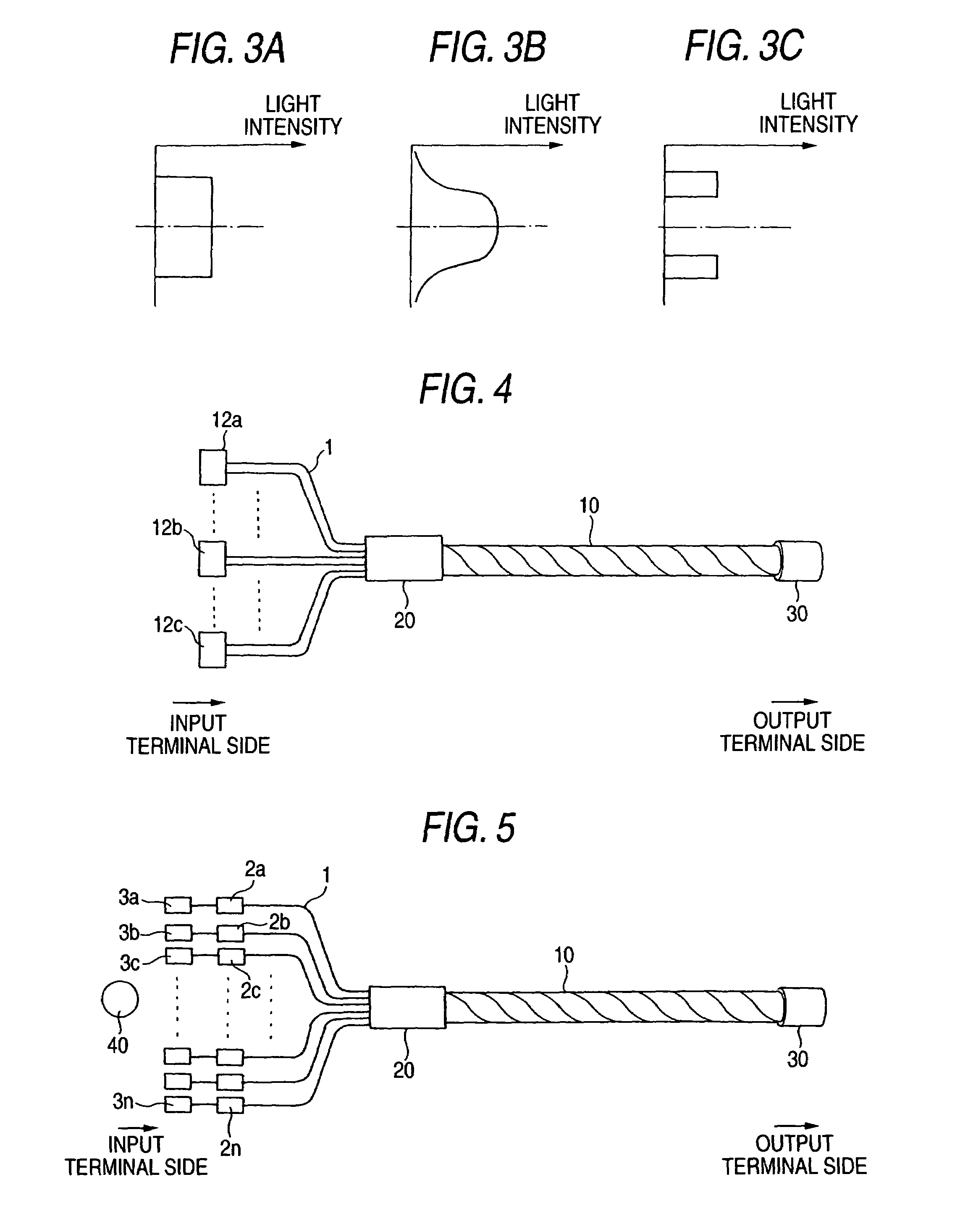
[0104]Although the connecting members 2a, 2b, 2c, . . . , 2n were attached to the optical fiber individually in the optical fiber bundle according to the first embodiment, the second embodiment has a feature in that optical fiber are paired, and connecting members 12a, 12b, . . . , 12n are connected to the pairs respectively as shown in FIG. 4. The other portions are formed in the same manner as those in the first embodiment.
[0105]In such a manner, connection on the input terminal side becomes easier so that manufacturing becomes easier, and control also becomes easier. While manufacturing becomes easier, the accuracy is a little inferior to that in the first embodiment.
third embodiment
[0106]Next, a third embodiment of the invention will be described.
[0107]In this embodiment, description will be made on a light source device using the optical fiber bundle according to the first embodiment.
[0108]This light source device has a feature in that light intensity adjusting members 3a, 3b, 3c, . . . , 3n are connected to connecting members 2a, 2b, 2c, . . . , 2n attached to optical fiber individually so that light from a white lamp light source 40 can be adjusted to have a desired light intensity by the light intensity adjusting members 3. The other portions are formed in the same manner as those in the first embodiment.
[0109]In such a manner, connection on the input terminal side becomes easier so that manufacturing becomes easier, and it is possible to obtain a light source device having a light intensity adjusted precisely.
PUM
| Property | Measurement | Unit |
|---|---|---|
| light intensity | aaaaa | aaaaa |
| light intensity distribution | aaaaa | aaaaa |
| flexibility | aaaaa | aaaaa |
Abstract
Description
Claims
Application Information
 - R&D
- Intellectual Property
- Life Sciences
- Materials
- Tech Scout
- Unparalleled Data Quality
- Higher Quality Content
- 60% Fewer Hallucinations
Browse by: Latest US Patents, China's latest patents, Technical Efficacy Thesaurus, Application Domain, Technology Topic, Popular Technical Reports.
© 2025 PatSnap. All rights reserved.Legal|Privacy policy|Modern Slavery Act Transparency Statement|Sitemap|About US| Contact US: help@patsnap.com


