Pump

a technology of displacement pump and pump body, which is applied in the direction of positive displacement pump, piston pump, liquid fuel engine, etc., can solve the problems of less reliability of pump, large pressure loss, and low frequency of discharge-suction cycle of pump

Active Publication Date: 2006-06-13
SEIKO EPSON CORP
View PDF25 Cites 19 Cited by
  • Summary
  • Abstract
  • Description
  • Claims
  • Application Information

AI Technical Summary

Benefits of technology

[0069]The inlet flow path has a fluid resistor to cause a resistance of the operating fluid to be smaller when the operating fluid flows into the pump chamber than when the operating fluid flows out of the pump chamber. The driving device drives the actuator so that a time during which pressure inside the pump is less than a suction-side pressure is equal to or greater than 60% of one period of movement of the diaphragm.
[0070]The suction time in the pump becomes long, so that a larger amount of fluid can be sucked into the pump chamber from the inlet flow path.
[0071]A combined inertance of the at least one inlet flow path is smaller than a combined inertance of the at least one outlet flow path, so that discharge flow rate can be increased, which is desirable.

Problems solved by technology

However, in the structure disclosed in JP 357, a check valve is required at both the inlet flow path and at the outlet flow path, so that, when fluid passes through the two check valves, pressure loss is large.
In addition, since the check valves repeatedly open and close, they may get fatigued and damaged, so that the larger the number of check valves used, the less the reliability of the pump.
Therefore, frequency of a discharge-suction cycle of the pump becomes considerably low.
However, in the structure disclosed in JP 537, since, as mentioned above, the pump can only be driven at a low frequency, a small pump having a high output cannot be provided.

Method used


Image

  • Pump
  • Pump
  • Pump

Examples


Embodiment Construction

[0090]Hereunder, a description of exemplary embodiments of the present invention is provided based on the drawings.

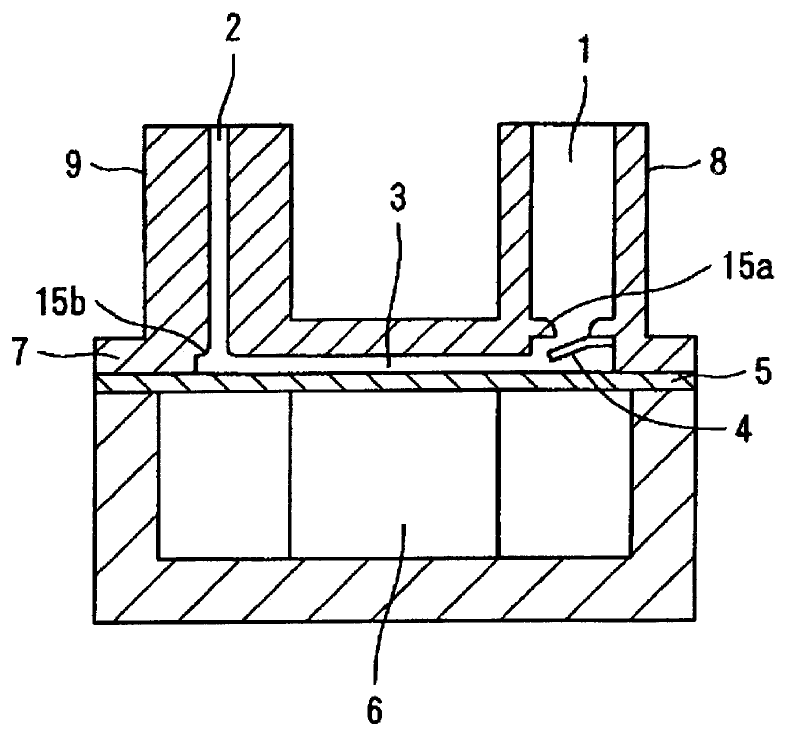
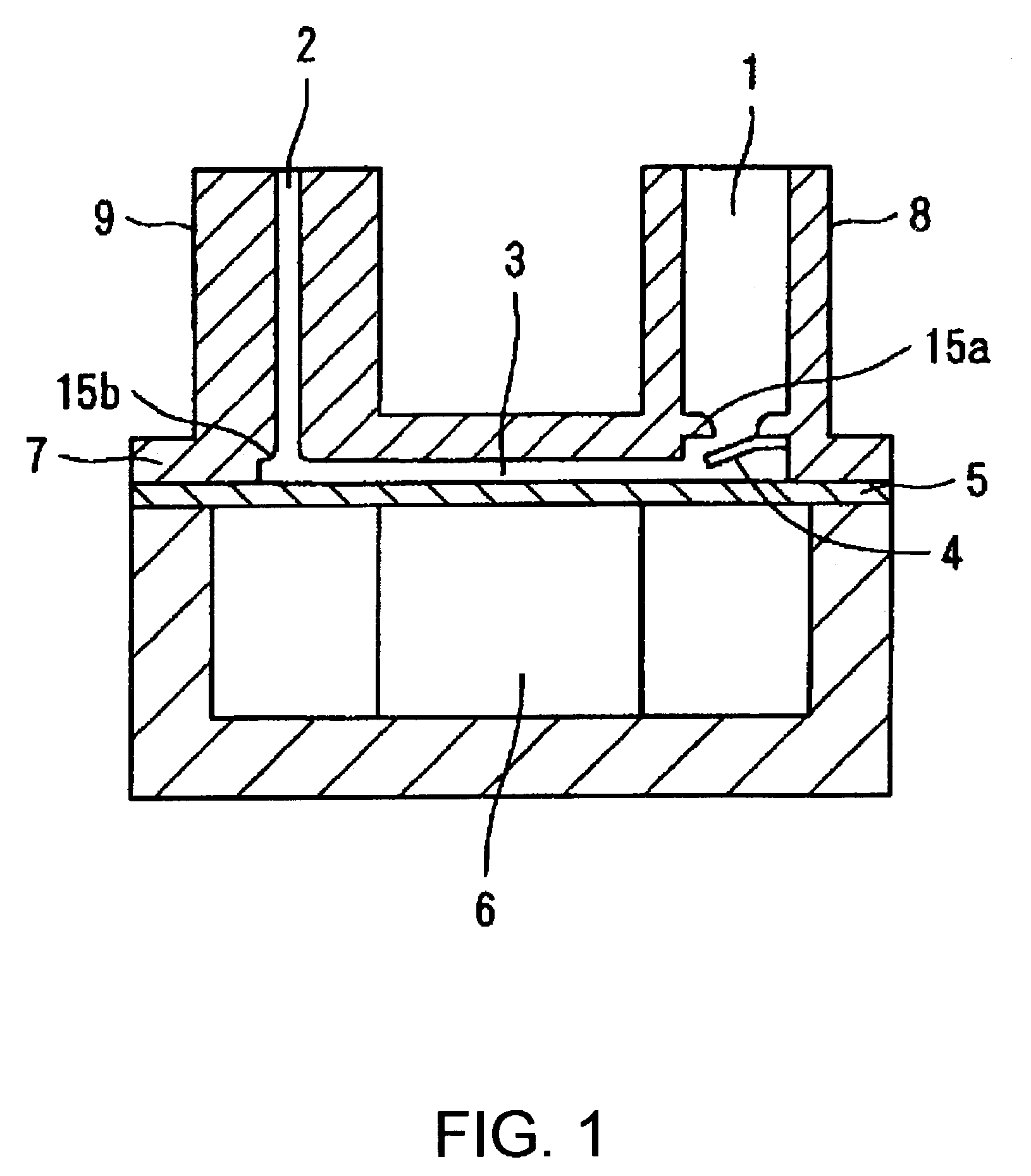
[0091]First, the structure of a pump of a first exemplary embodiment of the present invention is described with reference to FIG. 1.

[0092]FIG. 1 is a vertical sectional view of the pump of the present invention. A circular diaphragm 5 is disposed at the bottom portion of a circular cylindrical case 7. The outer peripheral edge of the diaphragm 5 is secured to and supported at the case 7 so as to be elastically deformable. A piezoelectric device 6 which serves as an actuator to move the diaphragm 5 and which expands and contracts vertically in FIG. 1 is disposed at the bottom surface of the diaphragm 5.

[0093]A narrow space between the diaphragm 5 and the top wall of the case 7 is a pump chamber 3. An inlet flow path 1, which has a check valve 4 that is a fluid resistor provided thereat, and an outlet flow path 2, which is a conduit having a small hole that always opens t...


PUM


Abstract

The invention provides a pump which has reduced pressure loss by using fewer mechanical on-off valves, which has increased reliability, which can be used under a high load pressure, which can be driven at a high frequency, and which has good drive efficiency by increasing discharge fluid volume per pumping period. A circular diaphragm, disposed at the bottom portion of a case, has its outer peripheral edge secured to and supported by the case. A piezoelectric device to move the diaphragm is disposed at the bottom surface of the diaphragm. A space between the diaphragm and the top wall of the case is a pump chamber. An inlet flow path, having a check valve serving as a fluid resistor disposed thereat, and an outlet flow path, which opens to the pump chamber during operation of the pump, open towards the pump chamber. In the pump, driving of the piezoelectric device is controlled so that an average displacement velocity in a pump chamber volume reducing step of the diaphragm becomes a velocity at which the diaphragm reaches the reached-displacement-position in a time equal to or less than ½ and equal to or greater than 1/10 of a natural vibration period T of fluid inside the pump chamber and the outlet flow path.

Description

BACKGROUND OF THE INVENTION[0001]1. Field of Invention[0002]The present invention relates to a positive displacement pump to move fluid by changing the volume inside a pump chamber by, for example, a piston or a diaphragm. More particularly, the invention relates to a highly reliable pump having a high flow rate.[0003]2. Description of Related Art[0004]Such a related art pump of this type generally has a structure that includes a check valve mounted between an inlet flow path and a pump chamber whose volume can be changed and between an outlet flow path and the pump chamber, as disclosed in Japanese Unexamined Patent Application Publication No. 10-220357 (JP 357).[0005]The related art also includes a pump structure to cause fluid to flow in one direction by making use of viscosity resistance of the fluid. This structure includes a valve at an outlet flow path. In this structure, fluid resistance at an inlet flow path is greater than at the outlet flow path when the valve is opened, ...

Claims


Application Information

Patent Timeline
Patent Type & Authority Patents(United States)
IPC IPC(8): F04B17/03F04B49/06F04B9/00F04B39/10F04B53/10
CPCF04B53/1077F04B39/1093
Inventor TAKAGI, KUNIHIKOSETO, TAKESHI
Owner SEIKO EPSON CORP
Why Eureka
Try Eureka