
Devices and methods for controlling initial movement of an electrosurgical electrode

a technology of electrodes and devices, applied in the field of electrosurgical electrode systems, can solve the problems of unfavorable user-based control, too fast effect,

Active Publication Date: 2006-06-13
CILAG GMBH INT
View PDF22 Cites 158 Cited by
  • Summary
  • Abstract
  • Description
  • Claims
  • Application Information

AI Technical Summary

Benefits of technology

[0014]The methods of the present invention also relate to controlling the operation of a percutaneously-placed electrosurgical electrode of an electrosurgical device. Energy is first delivered to a percutaneously-placed electrosurgical electrode to create an arc at that location, while the electrode is stationary. The electrical characteristics associated with the electrosurgical electrode are then monitored. The electrical characteristic being monitored may be any one, or a combination, of the following: electrical impedance, a change in electrical impedance, voltage, a change in voltage, current, or a change in current. Once the creation of a cutting arc is established between the adjacent tissue and the electrode, the controller initiates movement of the electrode to effect separation of the tissue section from the surrounding tissue. The energy being delivered to the electrosurgical electrode may then be adjusted based upon the monitoring step in an effort to help maintain an effective arc.

Problems solved by technology

With a percutaneous procedure, in particular an automated, percutaneous procedure, this type of user-based control is not possible, since the electrode is, in many cases, not visible.
And in the case of automated control, the effects occur too quickly to allow human reaction.

Method used


Image

  • Devices and methods for controlling initial movement of an electrosurgical electrode
  • Devices and methods for controlling initial movement of an electrosurgical electrode
  • Devices and methods for controlling initial movement of an electrosurgical electrode

Examples


Embodiment Construction

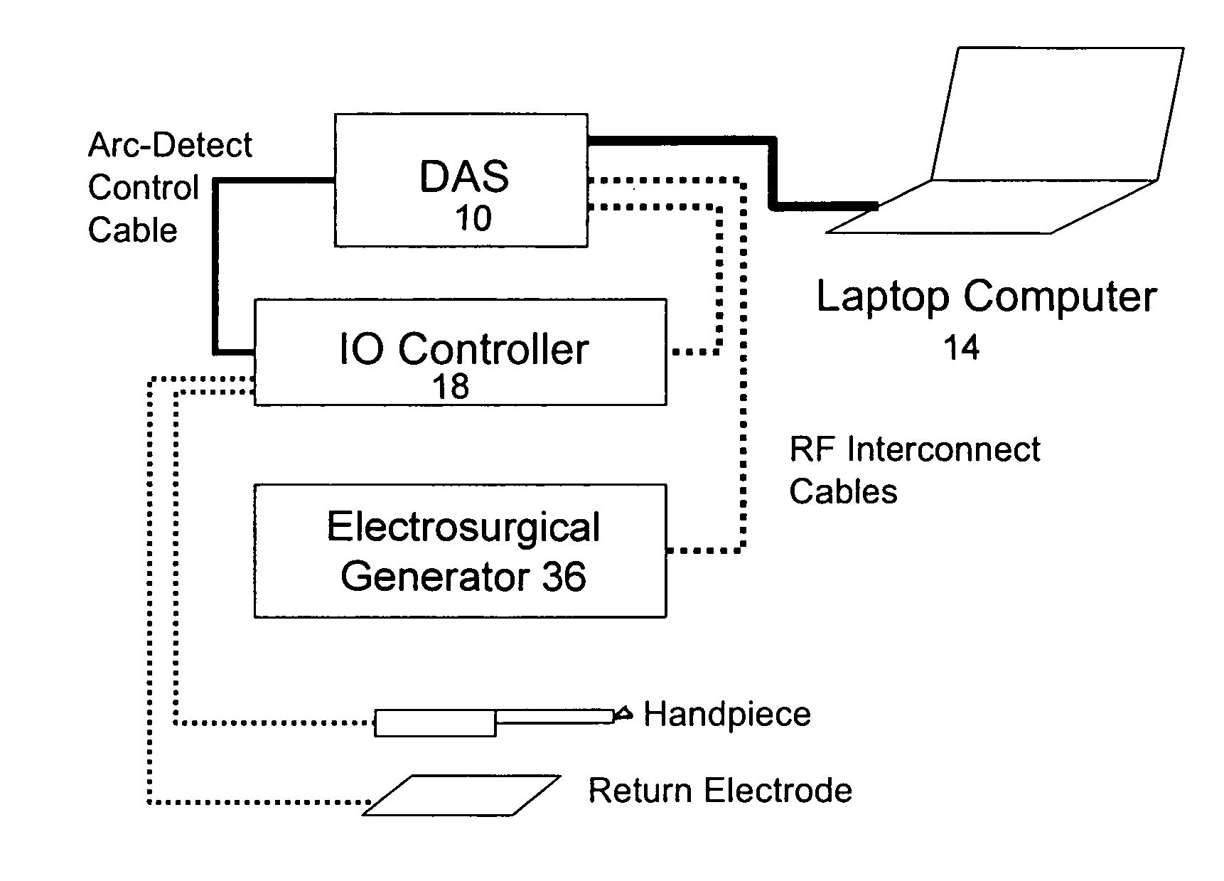
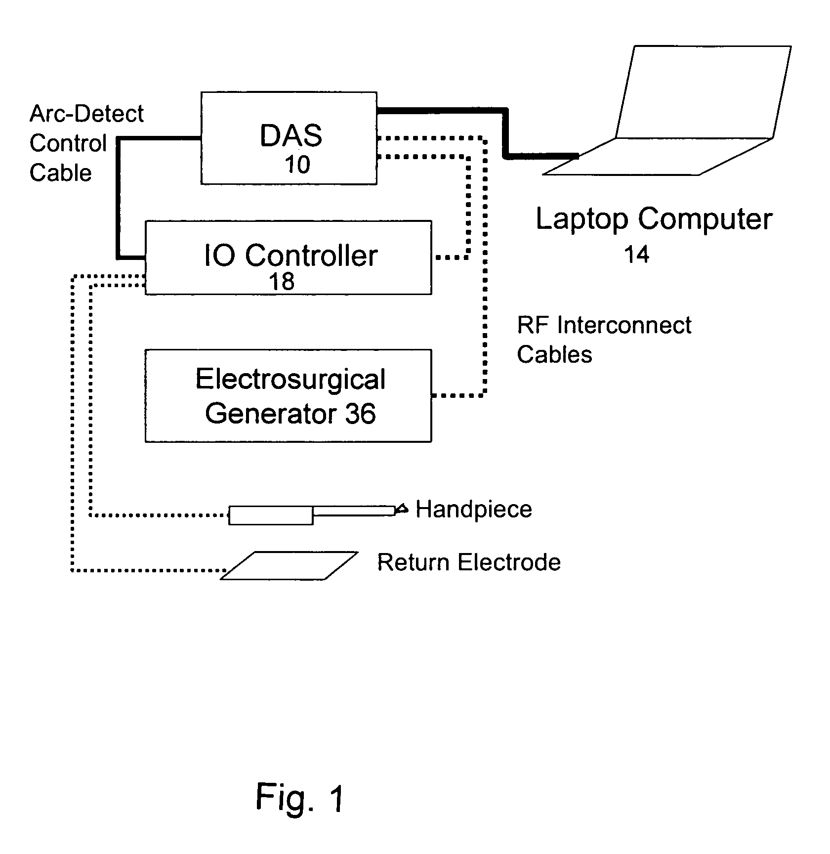
[0022]A first embodiment uses a commercially available RF generator along with an “IO” Control Box that controls the RF output to the electrode or loop-type cutter and contains a stepper motor drive to deploy and rotate the loop electrode. The RF activation, loop deployment and rotation are an automated sequence controlled by a stepper motor drive unit within the IO controller. One activation technique includes actuating the RF for approximately 400 milliseconds prior to the start of the deployment / rotation of the loop, in order to allow time for an arc to be established at the loop electrode. (There is an additional 100 millisecond delay induced by the loop deployment mechanism, for a total delay of 500 milliseconds.) This type of open loop operation causes two potential areas of inefficiency. First, the arc could be created early in the 500 millisecond period, causing excessive damage to the tissue while the electrode is arcing prior to the start of deployment / rotation. The second...


PUM


Abstract

An electrosurgical electrode assembly having a cutting device including a catheter with a proximal and distal end, and an electrode carried on the distal end of the catheter. A controller is connected to the cutting device. A data acquisition system is connected to the controller and is capable of monitoring voltage and current output. A microprocessor may also be connected to the data acquisition system for processing voltage and current data from the data acquisition system. A generator is also connected to the data acquisition system. The controller initiates movement of the electrode upon arc initiation at the electrode. Methods of using the devices herein are also disclosed.

Description

[0001]This application claims priority to U.S. Provisional Application Serial No. 60 / 426,030, filed on Nov. 13, 2002. This invention relates to devices and methods that may, but do not necessarily, involve the use of a target tissue localization device, such as shown in U.S. application Ser. No. 09 / 677,952, filed Oct. 2, 2000, now issued as U.S. Pat. No. 6,325,816, in conjunction with an electrosurgical loop-type cutter, such as shown in U.S. application Ser. No. 09 / 844,661, filed Apr. 27, 2001; U.S. application Ser. No. 09 / 588,278, filed Jun. 5, 2000, now issued as U.S. Pat. No. 6,530,278; and U.S. application Ser. No. 10 / 045,657, filed Nov. 7, 2001. All of the above-mentioned patents and applications are herein expressly incorporated by reference in their entirety.FIELD OF THE INVENTION[0002]The present invention relates generally to an electrosurgical electrode system that is capable of excising a tissue sample through the creation of an arc at the electrode.BACKGROUND[0003]Typic...

Claims


Application Information

Patent Timeline
Patent Type & Authority Patents(United States)
IPC IPC(8): A61B18/04A61BA61B18/14A61B18/18
CPCA61B18/1492A61B18/1206A61B2018/00208A61B2018/00601A61B2018/00702A61B2018/1861A61B2018/00827A61B2018/00875A61B2018/00892A61B2018/1213A61B2018/1407A61B2018/00779
Inventor MARION, DUANE W.MORRISON, GEORGE A.SCHOLL, JOHN A.SMITH, JEFFREY A.
Owner CILAG GMBH INT
Learn More