Distal targeting of locking screws in intramedullary nails

a technology of intramedullary nails and drilling screws, which is applied in the field of intramedullary nails, can solve the problems of difficult localization, unsatisfactory approach, and technical difficulties of the procedur

Active Publication Date: 2006-06-13
BIOSENSE
View PDF119 Cites 105 Cited by
  • Summary
  • Abstract
  • Description
  • Claims
  • Application Information

AI Technical Summary

Benefits of technology

[0014]It is therefore a primary object of some aspects of the present invention to provide a compact handheld unit including magnetic field generators to localize bores in an orthopedic appliance such as an intramedullary nail.
[0018]These and other objects of the present invention are attained by a distal targeting system, wherein a hand-held location pad is integral with a guide section for a drill or similar surgical instrument. The system employs magnetic field generators and magnetic field sensors, which can be wired or wireless. Either a sensor or a generator is disposed in an orthopedic appliance, such as an intramedullary nail. The sensor is capable of detecting and discriminating the strength and direction of a magnetic field. Control circuitry, preferably located in the location pad is responsive to a signal of the sensor, and determines the displacement and relative directions of an axis of the guide section and a bore in the orthopedic appliance. A screen display and optional speaker in the location pad provide an operator-perceptible indication that enables the operator to adjust the position of the guide section so as to align its position and direction with the bore.

Problems solved by technology

The procedure has presented technical difficulties, as the pre-drilled holes in the nail are not generally visible to the surgeon, and are difficult to localize and to align with surgical drills and placement instruments, so as to receive the locking members.
This approach has proven to be unsatisfactory, due to difficulties in obtaining precise alignment, and maintaining alignment without unduly increasing radiation exposure of the operator, other operating room personnel, and the patient.
Attempts to limit radiation exposure by offsetting the drill from the X-ray beam have also not been entirely successful.
The use of such procedures has often extended operating time and has increased operative risk and mortality.
This arrangement does not provide an indication of a desired direction to move a surgical tool, and is relatively insensitive to deviations when the tool is near an optimum location.
This arrangement is somewhat inconvenient for the operator, as it is continually necessary to reference the display, or to obtain callouts from an assistant viewing the fixed console.

Method used


Image

  • Distal targeting of locking screws in intramedullary nails
  • Distal targeting of locking screws in intramedullary nails
  • Distal targeting of locking screws in intramedullary nails

Examples


first embodiment

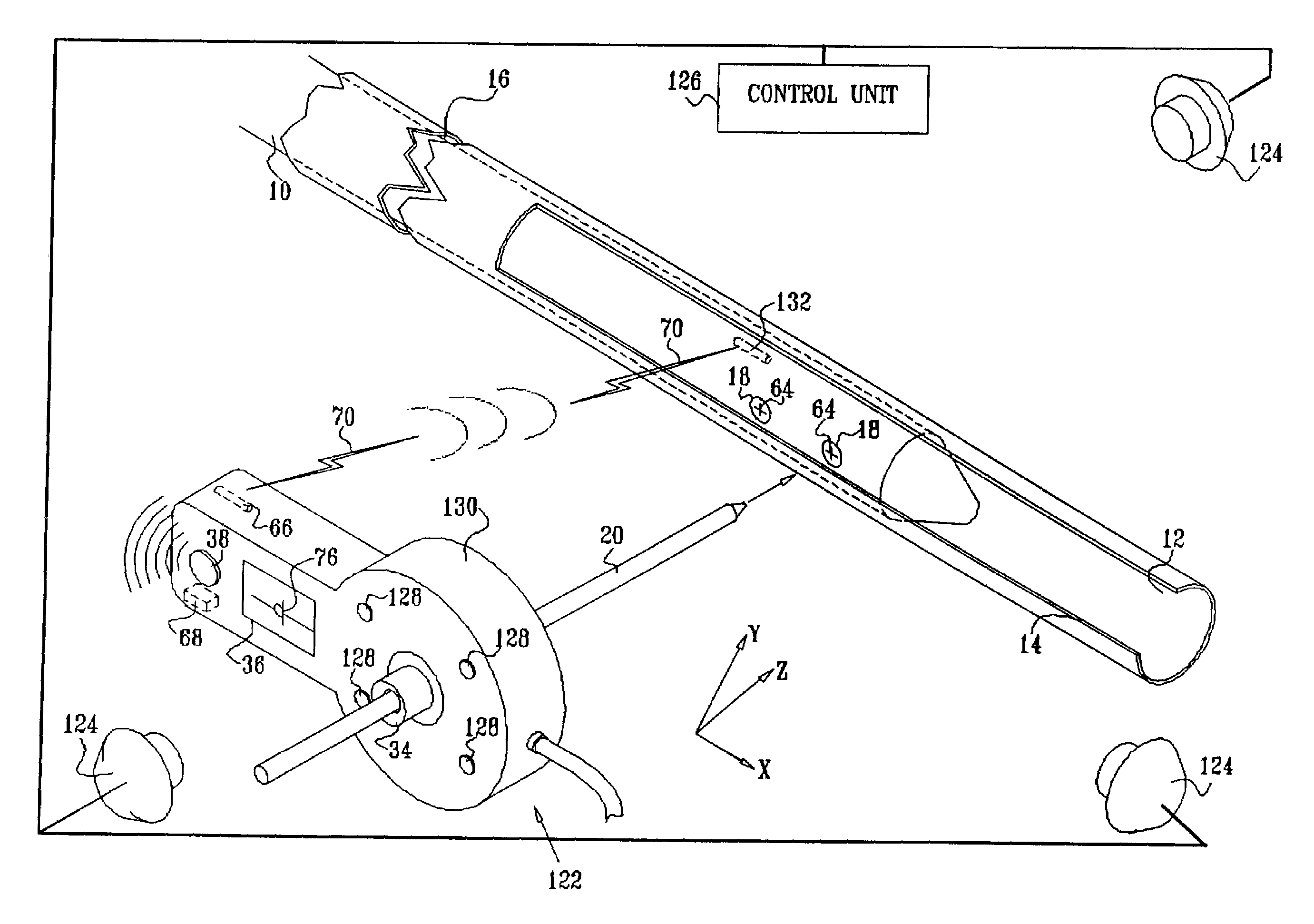
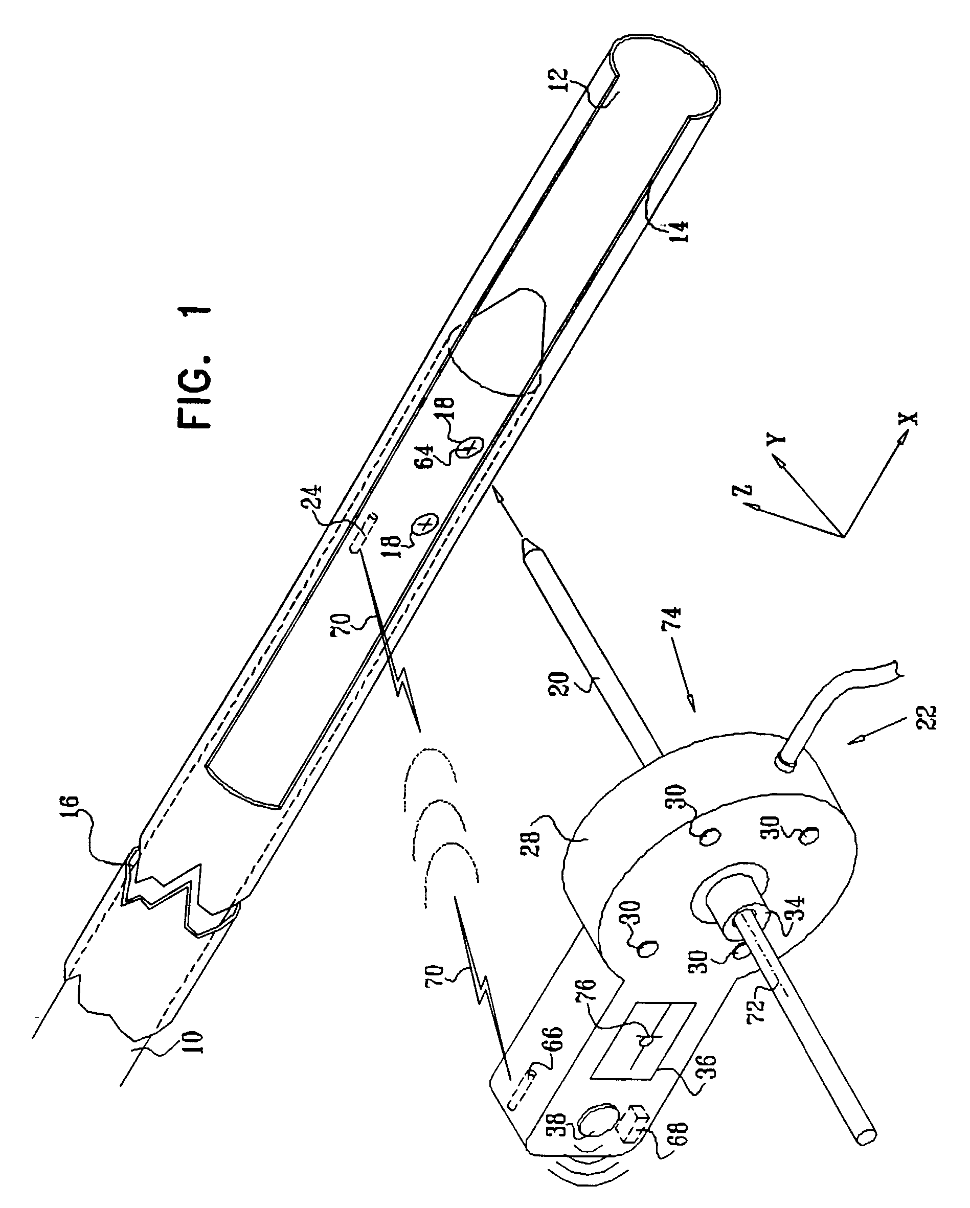
[0084]Turning now to the drawings, reference is made to FIG. 1, which is a schematic illustration of a distal targeting system which is constructed and operative in accordance with a preferred embodiment of the invention. A hollow appliance, preferably an intramedullary nail 10, is suitably dimensioned to a medullary cavity 12 of a bone 14 for the purpose of stabilizing a fracture 16. The intramedullary nail 10 is provided with at least one bore 18 for receiving a locking member 20 therethrough. The locking member 20 is typically realized as a wire or set screw, and must be inserted by the operator without benefit of direct visualization of the bore 18.

[0085]A magnetic field positioning arrangement 22 enables the operator to localize the bore 18 and to align the locking member 20 with the bore 18 prior to insertion therein. A miniature magnetic sensor 24 is disposed in the intramedullary nail 10, at known positional and rotational offsets from a principal axis 64 of the bore 18. In ...

second embodiment

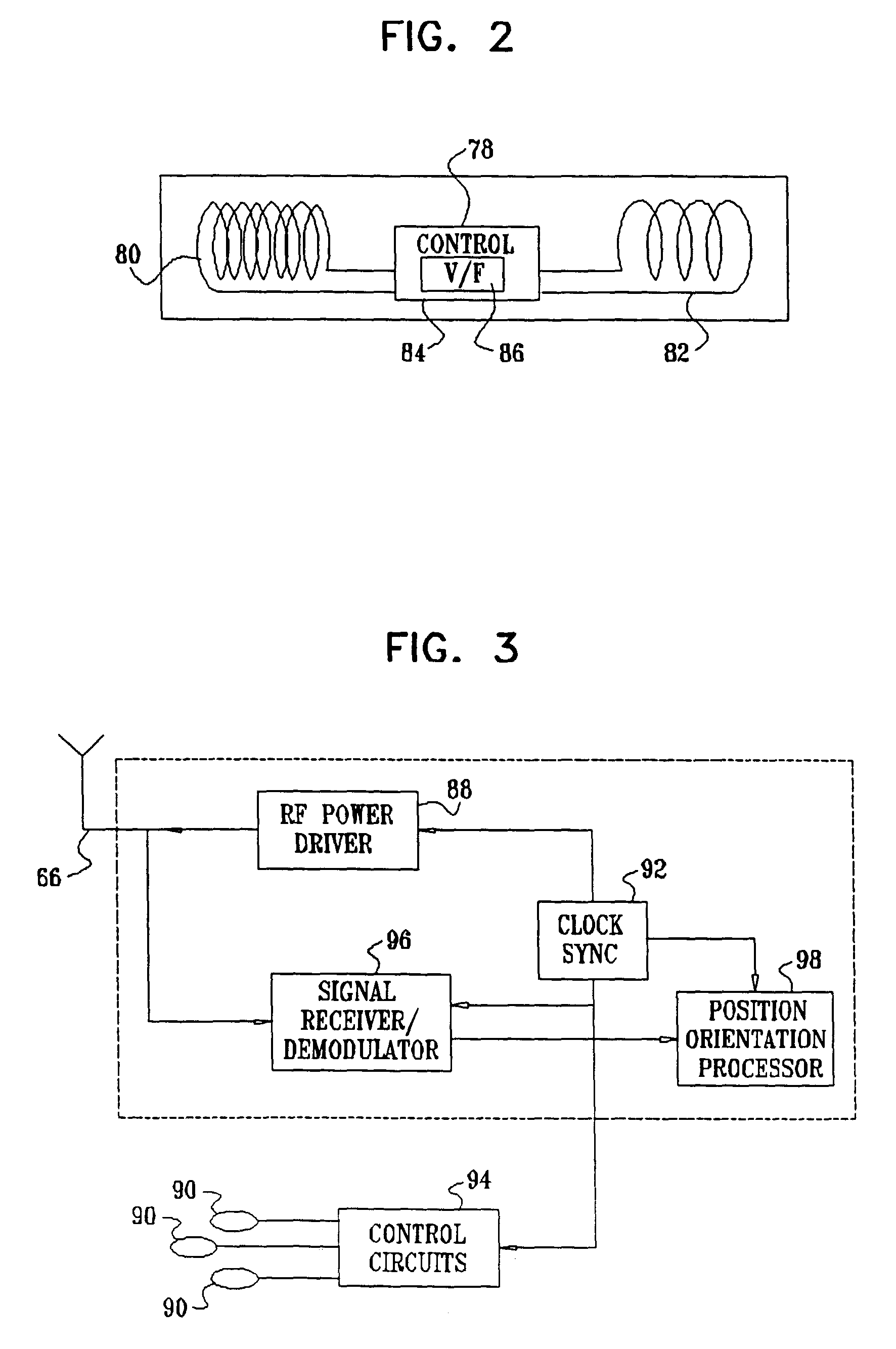
[0106]Reference is now made to FIG. 7, which is a schematic illustration of a distal targeting system which is constructed and operative in accordance with an alternate embodiment of the invention. Elements in FIG. 7 that are identical to those of FIG. 1 are given like reference numerals. In this embodiment, a magnetic field positioning arrangement 112 has a wired magnetic sensor 114, in place of the wireless sensor 24 (FIG. 1). Leads 26 are provided for powering the sensor 114 and obtaining a readout or other data therefrom. Leads 32 are provided to carry signals to a location pad 118 from the sensor 114. The location pad 118 is similar to the location pad 28 (FIG. 1), except that the location pad 118 requires no antenna or wireless receiving circuitry.

[0107]Reference is now made to FIG. 8, which is an enlarged fragmentary schematic view of the sensor 114 (FIG. 7). Three identical sensor coils 120, which can be wound on air cores or magnetic cores, are disposed within the sensor 11...

third embodiment

[0108]Reference is now made to FIG. 9, which is a schematic illustration of a distal targeting system which is constructed and operative in accordance with an alternate embodiment of the invention. Elements in FIG. 9 that are identical to those of FIG. 1 are given like reference numerals. A magnetic field positioning arrangement 122 is similar to the magnetic field positioning arrangement 22 (FIG. 1), except now, there are three or more external field generators 124, driven by a control unit 126. The field generators 124 are preferably fixed to the operating table or to another non-moving fixture, and provide an absolute frame of reference. Using this embodiment, an absolute position of the sensor can be obtained. As is explained in further detail below, different variations of this embodiment are possible. It is possible to exchange the roles of the sensor and the magnetic field generator modules. Thus in one variation, magnetic field generator modules and sensor can be located as ...


PUM


Abstract

In a distal targeting system a hand-held location pad is integral with a guide section for a drill or similar surgical instrument, and has a plurality of magnetic field generators. A sensor, such as a wireless sensor, having a plurality of field transponders, is disposed in an orthopedic appliance, such as an intramedullary nail. The sensor is capable of detecting and discriminating the strength and direction of the different fields generated by the field generators. Control circuitry, preferably located in the location pad is responsive to a signal of the sensor, and determines the displacement and relative directions of an axis of the guide section, and a bore in the orthopedic appliance. A screen display and optional speaker in the location pad provide an operator-perceptible indication that enables the operator to adjust the position of the guide section so as to align its position and direction with the bore.

Description

BACKGROUND OF THE INVENTION[0001]1. Field of the Invention[0002]This invention relates to intramedullary nails for use in fracture management. More particularly, this invention relates to placement of locking members in intramedullary nails by improved intraoperative distal targeting.[0003]2. Description of the Related Art[0004]Since the development of intramedullary nails for use in orthopedic surgery to manage bone fractures, it has been common practice to fix the bone with respect to the nail by placing locking members through holes drilled through cortical bone in alignment with holes that are pre-drilled transversely in the nail. The procedure has presented technical difficulties, as the pre-drilled holes in the nail are not generally visible to the surgeon, and are difficult to localize and to align with surgical drills and placement instruments, so as to receive the locking members.[0005]Placement of the holes in the cortical bone under X-ray or fluoroscopic guidance has been...

Claims


Application Information

Patent Timeline
Patent Type & Authority Patents(United States)
IPC IPC(8): A61B17/17A61B17/58A61B17/00
CPCA61B17/1707A61B17/1725A61B2019/547A61B2090/397A61B17/00
Inventor GOVARI, ASSAFDAYAN, AVINOAMDAVISON, DALE G.FERRO, THOMAS G.
Owner BIOSENSE
Why Eureka
Try Eureka