Method for using an ultrasonic nozzle to coat a medical appliance

a technology of medical appliances and ultrasonic nozzles, which is applied in the direction of packaging foodstuffs, prosthesis, mechanical vibration separation, etc., can solve the problems of difficult to achieve coatings, and difficult to achieve uniform thickness coatings

Inactive Publication Date: 2006-06-13
BOSTON SCI SCIMED INC
View PDF8 Cites 31 Cited by
  • Summary
  • Abstract
  • Description
  • Claims
  • Application Information

AI Technical Summary

Benefits of technology

[0011]By using an ultrasonic coating nozzle, no atomizing pressure is required. This may eliminate the highly focused jet and the consequent shooting of stents at high velocity. There may be sufficient gas flow from the fluidization flow to distribute the atomized coating and keep the stents fluidized.

Problems solved by technology

Additionally, treatment of the afflicted part of the body may require a high concentration of therapeutic agent that may not be achievable by systemic administration.
Although these processes have been used to produce satisfactory coatings, they have numerous, associated potential drawbacks.
For example, it may be difficult to achieve coatings of uniform thicknesses, both on individual parts and on batches of parts.
Also, these coating processes may require that the coated part be held during coating, which may result in defects such as bare spots where the part was held and which may thus require subsequent coating steps.
Two of the issues facing gas suspension are the effect of the process on the mechanical integrity of the stent and the effect on the coating.
One cause of damage to the stent and the coating in a gas suspension coating process is the velocity of the stent as it is fluidized.
A gas suspension system utilizes a gas atomizing spray nozzle, which uses a jet of gas that can shoot stents at rapid speeds and can cause both coating and stent damage.
This velocity can damage a stent and coating as the stent impacts other stents and the inside of the vessel.
These issues may become more critical with more flexible stent designs.
One issue with mounting the spray nozzle at the base may be that the direction of the spray may be straight up.

Method used


Image

  • Method for using an ultrasonic nozzle to coat a medical appliance
  • Method for using an ultrasonic nozzle to coat a medical appliance
  • Method for using an ultrasonic nozzle to coat a medical appliance

Examples


Embodiment Construction

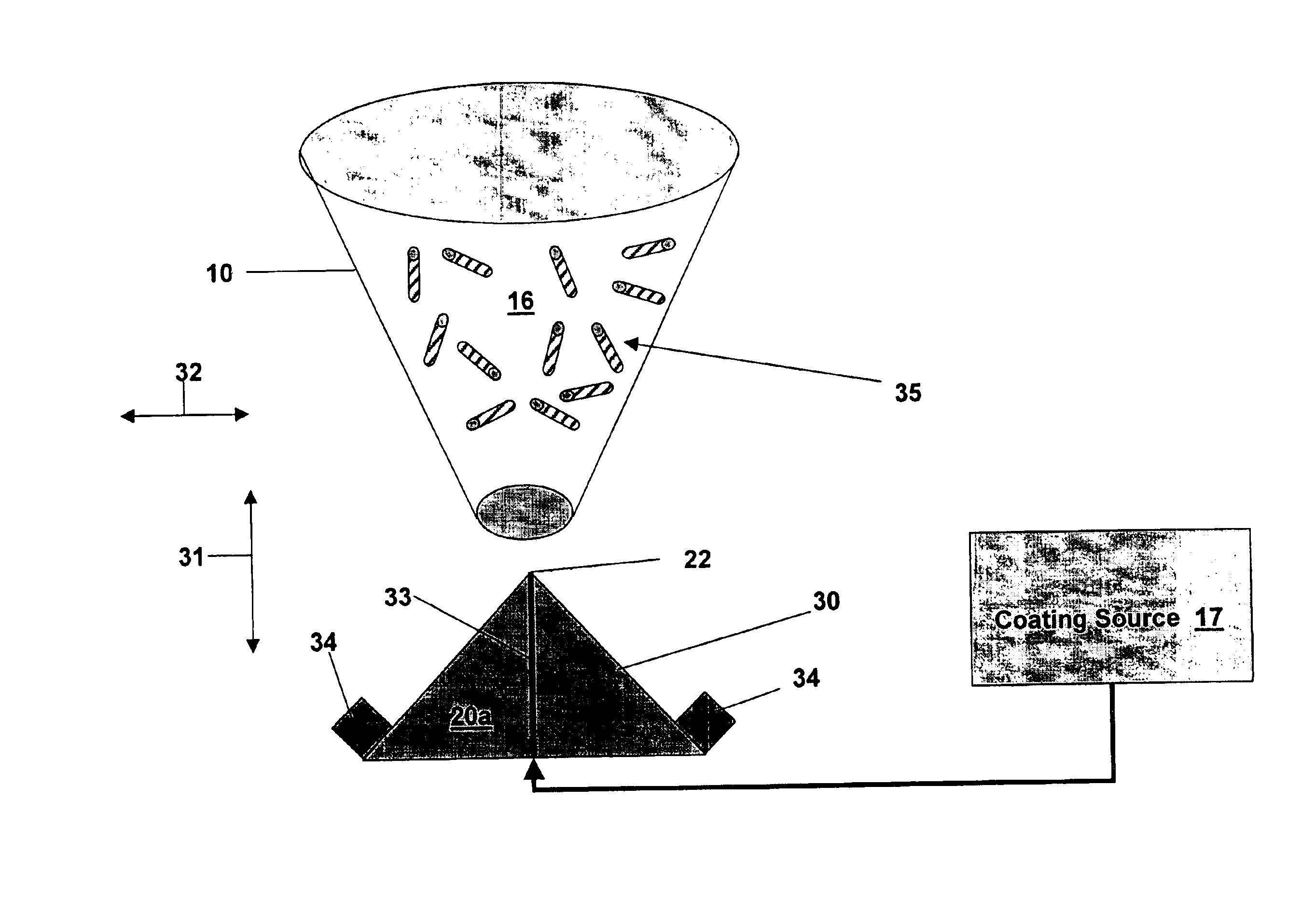
[0021]A major source of medical appliance velocity, and consequent medical appliance damage, during coating in an airstream coater is due to excessive gas velocity used to atomize the coating. The problem of damage to medical appliances during coating in an airstream coater due to excessive gas velocity may be eliminated if a different, less forceful, method of atomizing the coating is used. If the gas atomizing nozzle is replaced with an ultrasonic nozzle, which uses no gas pressure for atomization, then a major source of stent velocity may be eliminated. An ultrasonic atomizing nozzle may not require a jet of atomizing gas and, therefore, this type of coating system may be compatible with coating delicate items such as stents.

[0022]FIG. 1 shows hurricade 10 including atomizing gas nozzle 15. Positioned at the base of hurricade 10 is rotonozzle 11. Rotonozzle 11 may operate to cause the fluidizing gas flow to rotate or move in a particular manner, for instance in a particular direc...


PUM

PropertyMeasurementUnit
pressureaaaaaaaaaa
pressureaaaaaaaaaa
sizeaaaaaaaaaa

Abstract

A method for coating a medical appliance includes suspending the medical appliance with a fluidizing gas flow and directing a coating onto an ultrasonic nozzle. The ultrasonic nozzle is directed towards the medical appliance. The method also includes vibrating the ultrasonic nozzle at a rate sufficient to atomize the coating. A device for coating a medical appliance includes a fluidizing gas source adapted to suspend the medical appliance in a suspension area and an ultrasonic nozzle directed at the suspension area and adapted to vibrate. The device also includes a coating source adapted to direct coating onto the ultrasonic nozzle. A medical appliance is provided which has a coating applied by the method.

Description

FIELD OF THE INVENTION[0001]The present invention relates to the manufacturing of medical appliances. More particularly, the present invention relates to a device and method for coating medical appliances using an ultrasonic nozzle.BACKGROUND INFORMATION[0002]Medical devices may be coated so that the surfaces of such devices have desired properties or effects. For example, it may be useful to coat medical devices to provide for the localized delivery of therapeutic agents to target locations within the body, such as to treat localized disease (e.g., heart disease) or occluded body lumens. Localized drug delivery may avoid some of the problems of systemic drug administration, which may be accompanied by unwanted effects on parts of the body which are not to be treated. Additionally, treatment of the afflicted part of the body may require a high concentration of therapeutic agent that may not be achievable by systemic administration. Localized drug delivery may be achieved, for exampl...

Claims


Application Information

Patent Timeline
Patent Type & Authority Patents(United States)
IPC IPC(8): B05D1/02A61L27/00A61L31/10A61L31/16B05B7/00B05B13/02B05B17/06B05D1/22
CPCA61L31/10A61L31/16B05D1/22B05B13/025B05D1/02B05B7/0012A61L2300/00B05B17/06
Inventor FREDRICKSON, GERALD
Owner BOSTON SCI SCIMED INC
Why Eureka
Try Eureka