Rotor-stator structure for electrodynamic machines

a technology of rotating shafts and electrodynamic machines, which is applied in the direction of dynamo-electric machines, magnetic circuit rotating parts, and shape/form/construction of magnetic circuits, etc., can solve the problems of increasing the form factor of motors and materials, increasing the cost of materials to manufacture such motors, and increasing the return path of magnetic fields. , to achieve the effect of more output torque, shortening and straightening the magnetic path, and efficient use of materials

Active Publication Date: 2006-06-13
REGAL BELOIT AMERICA
View PDF179 Cites 45 Cited by
  • Summary
  • Abstract
  • Description
  • Claims
  • Application Information

AI Technical Summary

Benefits of technology

[0012]A system, apparatus and method are disclosed for implementing an exemplary rotor-stator structure for use in electrodynamic machines, such as electric motors, generators, alternators, and the like. According to one embodiment of the present invention, a rotor-stator structure for electrodynamic machines comprises conical magnets having conical surfaces arranged axially on an axis of rotation such that the conical surfaces face each other. The conical magnets include at least two conical magnets being positioned so that the directions of polarization of the two conical magnets are in substantially opposite directions. Further, the rotor-stator structure can also include field pole members arranged coaxially to the axis. The field pole members have flux interaction surfaces formed at the ends of the field pole members and adjacent to portions of the conical surfaces that confront the flux interaction surfaces. The flux interaction surfaces define air gaps with the portions of the conical surfaces and are configured to magnetically couple the field pole members to the conical magnets. In some cases, the rotor-stator structure includes a shaft on which the conical magnets are affixed, the shaft defining the axis of rotation. The conical surfaces each can have an angle of inclination from about 10 degrees to about 80 degrees with respect to the axis of rotation. In one embodiment, each of the field pole members further comprises a magnetically permeable material that is continuous from one end of each field pole member to the other end, where at least a portion of each field pole member is configured to accept an element, such as one or more coils, for generating ampere-turn (“AT”) flux. In an alternative embodiment, the rotor-stator structure further comprises one or more coils, at least one of which is wound about each of the field pole members to form active field pole members. In some cases, the rotor-stator structure excludes back-iron, thereby decreasing hysteresis losses as well as materials for manufacturing an electrodynamic machine. In another embodiment, at least one of the field pole members of a rotor-stator structure is substantially straight. Substantially straight field pole members can provide a relatively short magnetic flux path between magnets, which may be accompanied by a reduction in the volume of the magnetically permeable material as compared to the use of back-iron in some traditional stator structures. By reducing the volume of magnetically permeable material through which magnetic flux is conducted, hysteresis losses can be decreased.
[0013]The field pole members and the conical magnets of an exemplary rotor-stator structure can be arranged to minimize linear deviations in a path portion of a magnetic flux path coincident with a substantially straight line extending from a surface portion of a first conical magnet to a surface portion of a second conical magnet, the path portion terminating at the surface portions. In a specific embodiment, the rotor-stator structure is configured to generate magnetic flux paths consisting essentially of the first conical magnet, the second conical magnet, at least one of the field pole members, and two or more air gaps. The field pole members, in some instances, can comprise laminations to minimize eddy currents, thereby reducing power losses. The laminations can be formed from a substrate composed of a magnetically permeable material in a manner that reduces wastage of the magnetically permeable material. Notably, in certain instances, at least one of the laminations is anisotropic, which can include grain-oriented materials. In one embodiment, the rotor-stator structure further comprises a coil wound about at least one of the field pole members to form at least one active field pole member, where at least the one field pole member is shaped to minimize manufacturing complexity associated with winding the coil on traditional field poles by obviating the need to wind the coil via a slot. In still another embodiment, each of the flux interaction surfaces further comprises a skewed flux interaction surface to reduce field pole gaps between adjacent field pole members, thereby minimizing detent torque. Detent torque can also be reduced by offsetting the directions of polarization of the two conical magnets by about 150 to about 180 degrees. The field pole members, in at least one example of a rotor-stator structure, are stationary while the conical magnets can rotate relative to the field pole members, whereas in other examples, the conical magnets remain stationary and the field pole members rotate relative to the conical magnets.
[0015]According to yet another embodiment of the present invention, an exemplary rotor-stator structure for electrodynamic machines comprises a shaft defining an axis of rotation and having a first end portion, a central portion and a second end portion. The rotor-stator structure includes at least a first magnet having a surface contoured as at least a portion of a cone to form a first conical surface, the first magnet having a first direction of polarization and being disposed axially on the shaft at the first end portion. Also, the rotor-stator structure can include a second magnet having a surface contoured as at least a portion of a cone to form a second conical surface, the second magnet having a second direction of polarization and being disposed axially on the shaft at the second end portion such that the first direction of polarization is substantially opposite to the second direction of polarization. Generally, the second conical surface faces, or confronts, the first conical surface. The rotor-stator structure is further composed of a number of field pole members arranged substantially coaxial to the shaft. Each of the field pole members comprises a number of substantially straight laminations, at least one of which is composed of anisotropic material and arranged in parallel with other laminations and in parallel with the axis of rotation. Each of the field pole members has a first pole shoe at its first field pole member end and a second pole shoe at its second field pole member end, the first pole shoe being positioned adjacent to a portion of the first conical surface to form a first flux interaction region and the second pole shoe being positioned adjacent to a portion of the second conical surface to form a second flux interaction region. Further, the rotor-stator structure includes at least one coil wound about at least one of the number of field pole members to form an active field pole member. As such, at least in some cases, the rotor-stator structure is configured to generate at least one magnetic flux path limited to traverse only through the first magnet, the second magnet, the active field pole member and the first and second flux interaction regions. In a specific embodiment, the at least one coil extends substantially the length of the active field pole member in an axial direction for reducing flux leakage from the peripheries of the active field pole member.
[0018]According to at least one embodiment, an exemplary rotor-stator structure can be disposed within an electric motor to provide more output torque deliverable by such a motor relative to conventional electric motors of the same size and / or weight. In one embodiment, a rotor-stator structure provides a relatively shorter and straighter magnetic path, and a more efficient use of materials than traditional stator-rotor structures for electrodynamic machines. In cases where anisotropic (e.g., grain-oriented materials) lamination materials are used to form field pole members of specific embodiments of the present invention, the inherent magnetic properties of the laminations contribute to an increase of flux density in flux-carrying regions. The elimination or at least reduction in exterior return paths, such as those return paths traditionally implemented using back-iron, therefore saves weight and reduces the overall size of electrodynamic machines implementing various embodiments of the rotor-stator structure of the present invention. In another embodiment, a stator-rotor structure provides a greater motor efficiency than a similarly-sized conventional motor with the same output torque. This efficiency increase is due, at least in part, to lower resistance windings, which translates to lower current-squared-times-resistance (i.e., I2*R) power losses while producing the same ampere turn-generated flux created in similarly-sized packages or motor housings of traditional motors. Further, the rotor-stator structure of the present invention is less complex (e.g., in the coil winding process) and less costly (e.g., due to conservation of materials) to manufacture than conventional motors.

Problems solved by technology

One drawback of traditional electric motors, including electric motor 100, is that magnetic return path 116 requires a relatively long length for completing a magnetic circuit for flux emanating from one rotor magnet pole 110 and traversing via magnetic return path 116 to another rotor magnet pole 110.
Consequently, magnetic return paths 116 add weight and size to traditional electric motors, thereby increasing the motor form factor as well as cost of materials to manufacture such motors.
Another drawback of conventional electric motors is that laminations 114 do not effectively optimize the flux density in flux-carrying poles, such as through field poles 118 and stator regions at peripheral flux-carrying segment 119, due to hysteresis losses (or “iron losses”).
Consequently, anisotropic materials generally have not been implemented in structures similar to stator structure 104 since the flux paths are usually curvilinear rather than straight, which limits the benefits provided by using such materials.
Yet another drawback of conventional electric motors is the relatively long lengths of magnetic return path 116.
Eddy currents result in power losses that are roughly proportional to a power function of the rate at which the magnetic flux changes and roughly proportional to the volume of affected lamination material.
Other drawbacks of commonly-used electric motors include the implementation of specialized techniques for reducing “cogging,” or detent torque, that are not well-suited for application with various types of electric motor designs.
Cogging is a non-uniform angular torque resulting in “jerking” motions rather than a smooth rotational motion.
Further, the inherent rotational accelerations and decelerations cause audible vibrations.
A drawback to this approach is that additional materials are consumed in forming larger motor structures to accommodate the larger torque arm distance, such as those structures that are used to form magnetic flux return paths.
By adding back-iron to complete a magnetic circuit, the magnetic material volume through which the magnetic flux passes increases, which detrimentally tends to increase the hysteresis and eddy current losses, both of which can be collectively referred to as “core losses.” Further, the addition of back-iron to complete a magnetic circuit increases the magnetic flux path, thereby exacerbating core losses.
Another drawback to motors of this type is that the motor volume increases as the magnetic poles are positioned farther from the shaft, which in turn, limits the available applications and uses for this type of motor.
Further, “back-iron” structures are not generally formed to accept an associated ampere-turn generating element, such as one or more coils.

Method used


Image

  • Rotor-stator structure for electrodynamic machines
  • Rotor-stator structure for electrodynamic machines
  • Rotor-stator structure for electrodynamic machines

Examples


Embodiment Construction

Definitions

[0035]The following definitions apply to some of the elements described with respect to some embodiments of the invention. These definitions may likewise be expanded upon herein.

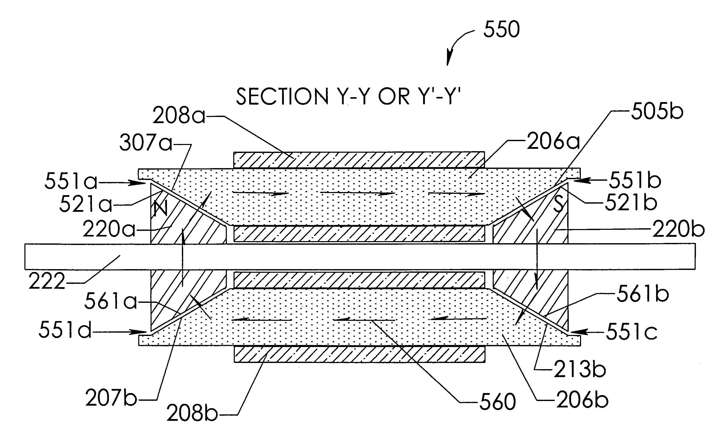
[0036]As used herein, the term “air gap” refers to a space, or a gap, between a magnet surface and a confronting pole face. Such a space can be physically described as a volume bounded at least by the areas of the magnet surface and the pole face. An air gap functions to enable relative rotation between a rotor and a stator, and to define a flux interaction region. Although an air gap is typically filled with air, it need not be so limiting.

[0037]As used herein, the term “back-iron” commonly describes a physical structure (as well as the materials giving rise to that physical structure) that is often used to complete an otherwise open magnetic circuit. In particular, back-iron structures are generally used only to transfer magnetic flux from one magnetic circuit element to another, such as either ...


PUM


Abstract

A rotor-stator structure for electrodynamic machinery is disclosed to, among other things, minimize magnetic flux path lengths and to eliminate back-iron for increasing torque and / or efficiency per unit size (or unit weight) and for reducing manufacturing costs. In one embodiment, an exemplary rotor-stator structure can comprise a shaft defining an axis of rotation, and a rotor on which at least two substantially conical magnets are mounted on the shaft. The magnets include conical magnetic surfaces facing each other and confronting air gaps. In some embodiments, substantially straight field pole members can be arranged coaxially and have flux interaction surfaces formed at both ends of those field poles. Those surfaces are located adjacent to the confronting conical magnetic surfaces to define functioning air gaps. Current in coils wound on the field poles provide selectable magnetic fields that interact with magnet flux in flux interaction regions to provide torque to the shaft.

Description

CROSS REFERENCE TO RELATED APPLICATION[0001]This application claims the benefit of U.S. Provisional Application No. 60 / 622,258, entitled “Rotor-Stator Structure for Electric Motors and Generators” and filed on Oct. 25, 2004, the disclosure of which is incorporated herein by reference in its entirety.BRIEF DESCRIPTION OF THE INVENTION[0002]This invention relates generally to electric motors, alternators, generators and the like, and more particularly, to a rotor-stator structure for motors that, for example, increases output torque per unit size (or per unit weight) either by minimizing the length of magnetic flux paths or by straightening those paths through anisotropic field pole members, or both. Further, the rotor-stator structure conserves resources, such as reducing manufacturing costs, such as by minimizing wastage and by eliminating “back-iron” material.BACKGROUND OF THE INVENTION[0003]In traditional stator and rotor structures for fractional and sub-fractional horsepower mot...

Claims


Application Information

Patent Timeline
Patent Type & Authority Patents(United States)
IPC IPC(8): H02K21/12
CPCH02K21/14H02K21/24H02K21/12
Inventor PETRO, JOHN PATRICKWASSON, KEN GEORGE
Owner REGAL BELOIT AMERICA
Why Eureka
Try Eureka