Circuit and method for measuring distances

Inactive Publication Date: 2006-06-13
MICRO EPSILON MESSTECHNIK GMBH & CO KG
View PDF12 Cites 43 Cited by
  • Summary
  • Abstract
  • Description
  • Claims
  • Application Information

AI Technical Summary

Benefits of technology

[0035]In a particularly simple manner, the output of the SC amplifier could be applied to the second input of the SC integrator. With that, the output signal could have a delay of one clock period.
[0036]The method of th

Problems solved by technology

However, these measurements are only seldom inserted into the normal measurements with the mere ac voltage input signals.
The known circuit is problematic in particular to the extent that the occurring time constants

Method used


Image

  • Circuit and method for measuring distances
  • Circuit and method for measuring distances
  • Circuit and method for measuring distances

Examples


Embodiment Construction

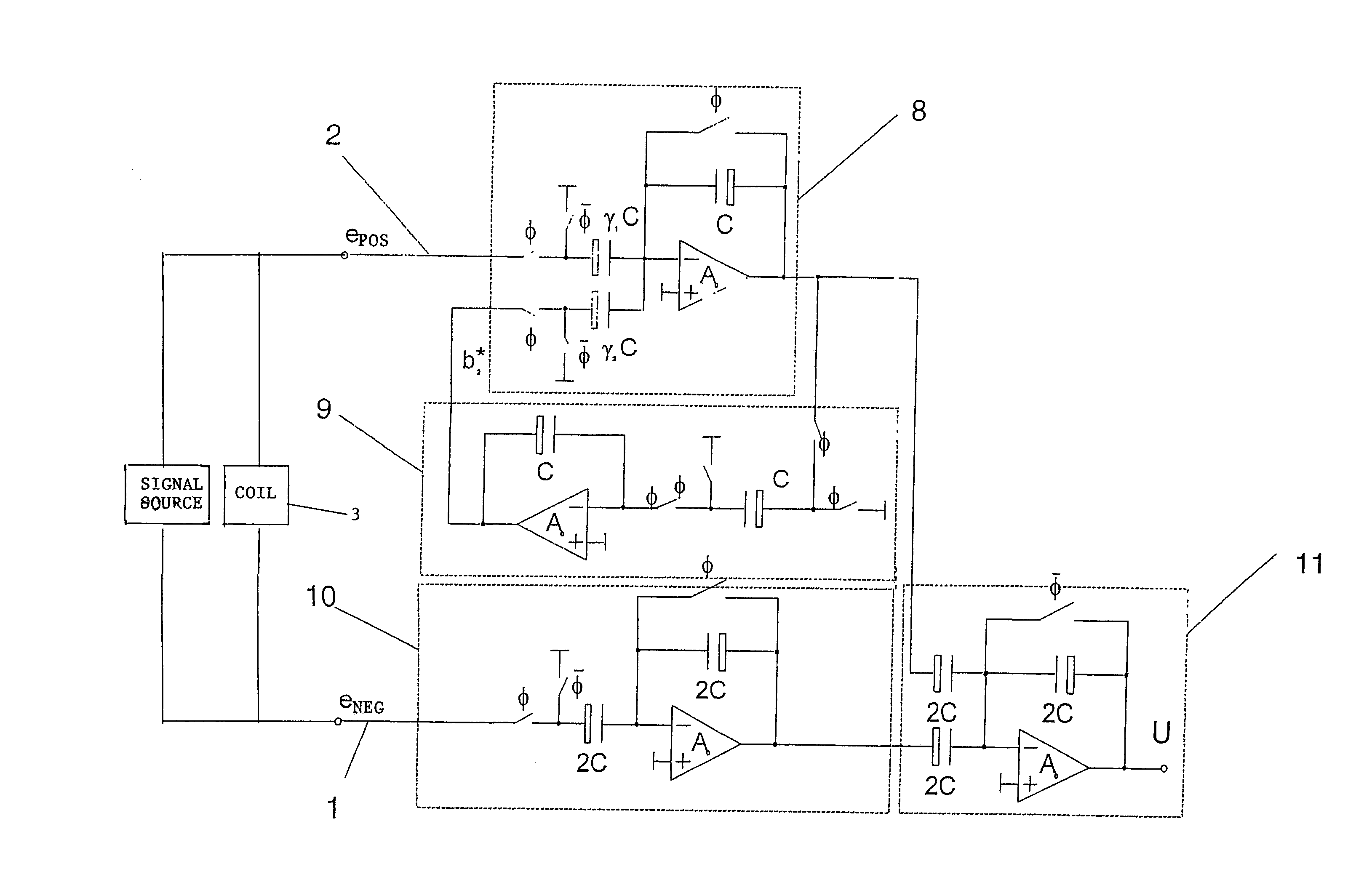
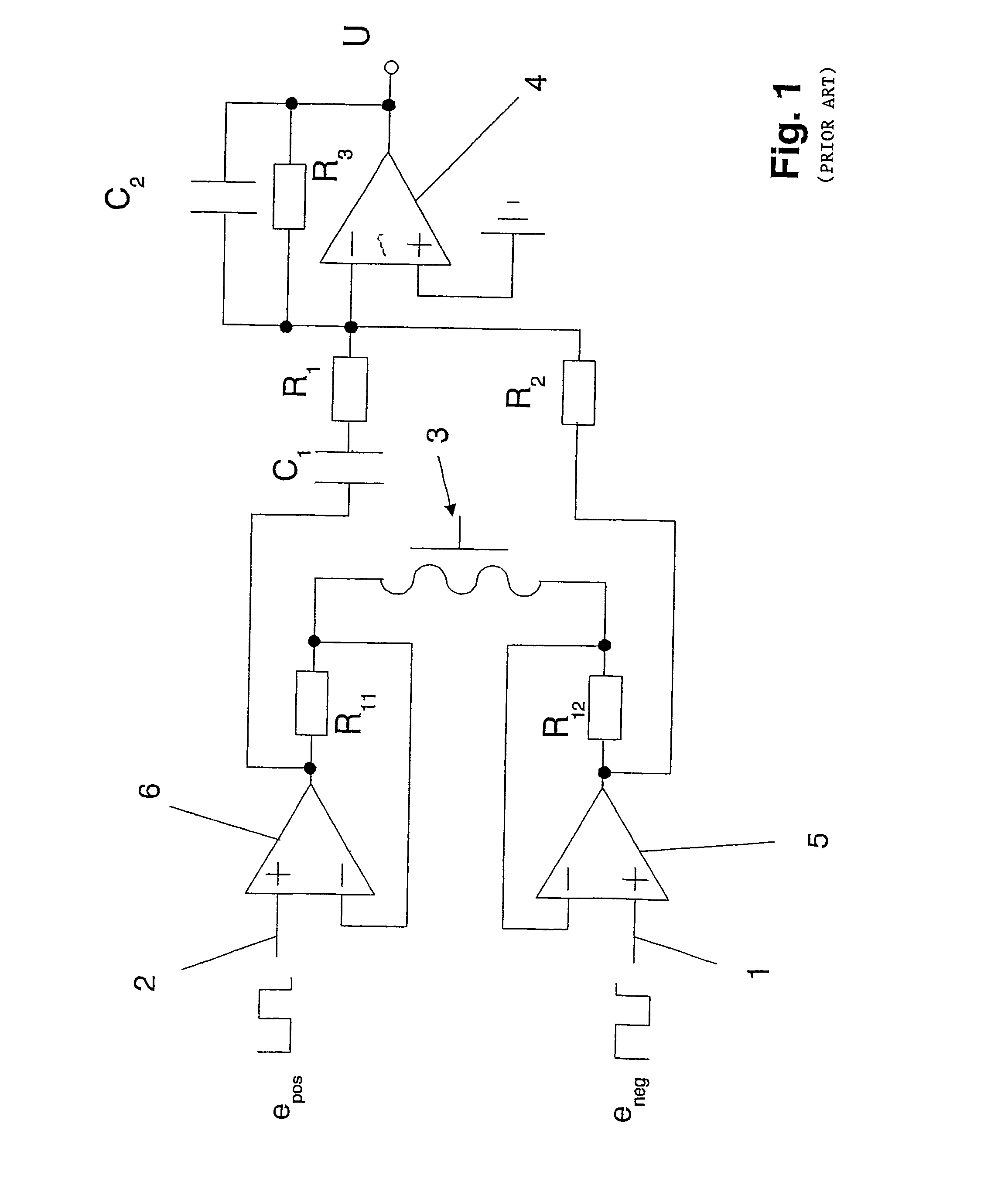
[0049]The known circuit for measuring distances is provided as a discrete circuit and comprises two inputs 1, 2, as well as a measuring coil 3. A signal source (not shown) permits generating two input signals epos and eneg. The inputs 1, 2 are activated by means of the input signals epos and eneg. The input signals epos and eneg are applied in a preprocessed form to the inputs 1, 2 of the measuring coil 3.

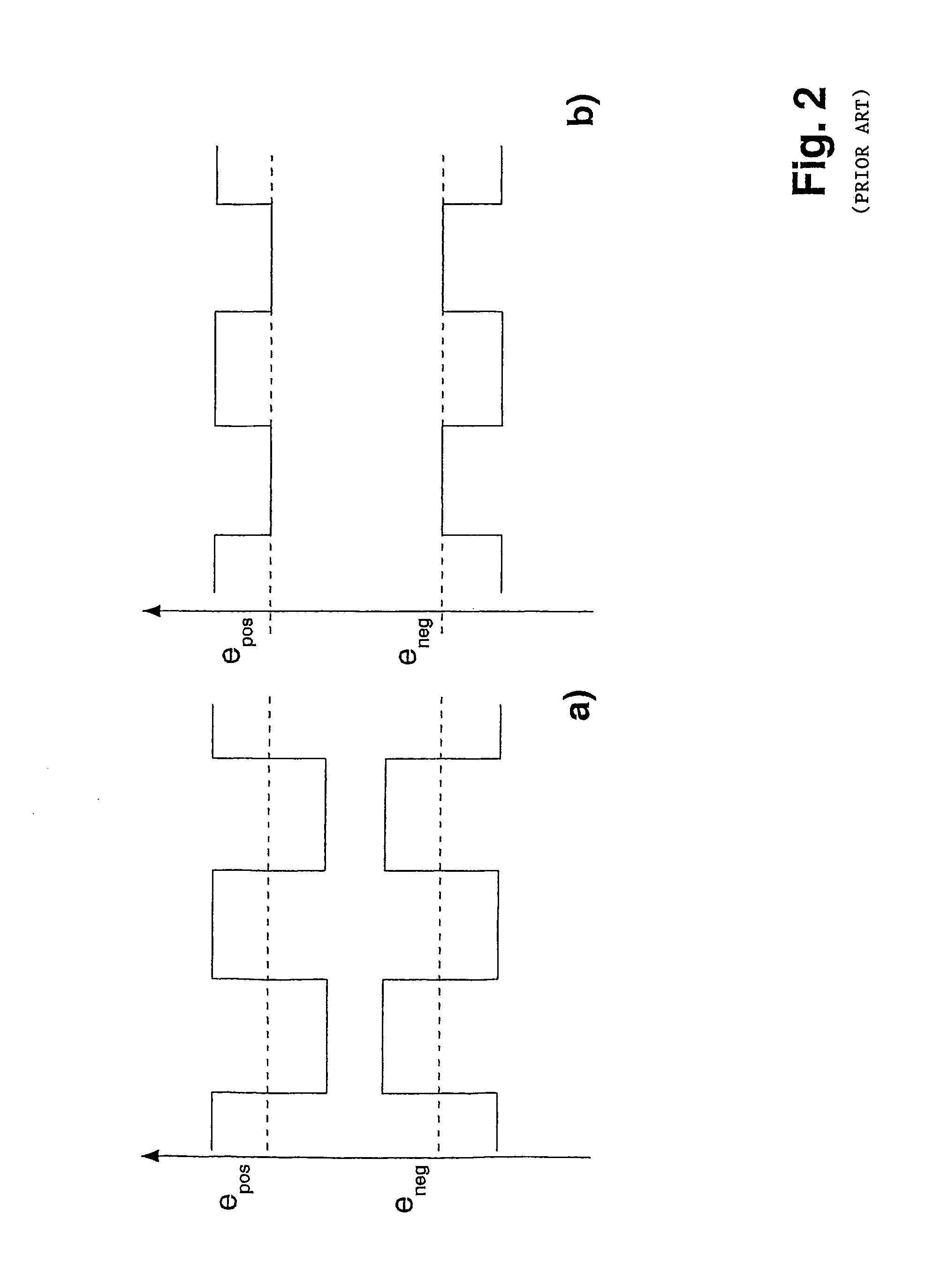
[0050]The known circuit that is excited by ac voltage makes it possible to determine by measuring a dc component, which is proportional to the temperature. Operational amplifiers that follow the inputs 1, 2 form with their resistors a voltage / current transformer. The current is coupled into the measuring coil 3 from both sides. In the normal operation, i.e., measuring operation, the ac signals epos and eneg shown FIG. 2a are used for activating the inputs. However, to determine a linearly dependent temperature behavior of the circuit and the measuring coil 3, one uses the input sig...


PUM


Abstract

A circuit for measuring distances and which has at least two inputs (1, 2), at least one measuring coil (3), and at least one signal source, wherein at least two input signals (epos, eneg) are generated by means of the signal source, and the inputs (1, 2) are activatable by means of the input signals (epos, eneg). The input signals (epos, eneg) are applied, preferably preprocessed, to the inputs of the measuring coil (3). The circuit is designed for use where little space is available for the circuit, with the input signals (epos, eneg) being applied to a preferably timed SC network, which generates a measuring output signal that is dependent on temperature. A corresponding method is also described.

Description

CROSS REFERENCE TO RELATED APPLICATION[0001]The present application is a continuation of international application PCT / DE02 / 03507, filed Sep. 19, 2002, and which designates the U.S. The disclosure of the referenced application is incorporated herein by reference.BACKGROUND OF THE INVENTION[0002]The invention relates to a circuit for measuring distances, of the general type disclosed in DE 42 25 968 A1 and corresponding U.S. Pat. No. 5,629,619. These prior patents disclose a circuit which is used to measure distances in a noncontacting manner by means of a measuring coil. The circuit is an inductive distance sensor, which is operated with relatively low frequencies in a range from 1 kHz to 10 kHz. To increase the accuracy of the measurement, it is necessary to determine the temperature influence on the measured value. In this known circuit, this occurs by means of a discrete circuit, which determines the dc voltage component with a circuit that is excited by ac voltages. The circuit ...

Claims


Application Information

Patent Timeline
IPC IPC(8): G01B7/14H03B1/00G01D5/14G01D3/028G01D5/20
CPCG01D3/028G01D5/202G01D5/2013
Inventor KLEINE, ULRICHROEWER, FALKSALZWEDEL, KLAUSMEDNIKOV, FELIXSELLEN, MARTIN
Owner MICRO EPSILON MESSTECHNIK GMBH & CO KG
Why Eureka
Try Eureka