Data transmission apparatus, system and method, and image processing apparatus

a data transmission and image processing technology, applied in the field of data transmission apparatus, system and method, image processing apparatus, can solve the problems of limited type and number of connectable peripheral devices, low data transfer rate, bulky communication cables, etc., and achieve the effect of high-efficiency data transfer

Inactive Publication Date: 2006-06-13
CANON KK
View PDF114 Cites 81 Cited by
  • Summary
  • Abstract
  • Description
  • Claims
  • Application Information

AI Technical Summary

Benefits of technology

[0027]The present invention has been made to solve the above problems, and has its object to provide a data transmission apparatus, system and method and an image processing apparatus, which perform high efficient data transfer by notifying information on data processing capability of a destination node of data transfer, from the destination node to a transfer originator node.
[0032]Further, another object of the present invention is to provide a data transmission apparatus, system and method and an image processing apparatus which separate control commands from data and attain high transfer efficiency.
[0033]Further, another object of the present invention is to provide a data transmission apparatus, system and method and image processing apparatus which remove overhead required for determining whether or not data can be written into a data transfer area.

Problems solved by technology

However, the above interface such as an SCSI interface has various inconveniences such as the low data transfer rate, the bulky communication cable, the limitation on the type and number of connectable peripheral devices, the limitation on connection methods and the like.
At such connector, attachment / detachment is troublesome.
For example, when a portable device such as a digital still camera or a video camera is connected to the PC, it is very tiresome to connect cables to the connector provided on the rear surface of the PC.
In this case, as the load on the overall network or the PC as a host device increases, the printing may not be normally performed or delayed.
In this manner, the trouble occurs in data communication on the network due to increase of the network traffic or in accordance with the operational status of the PC.
As described above, the image data outputted from the image providing device is converted into print data by the PC and print-outputted by the printer, accordingly, even if the image providing device and the printer are directly connected, printing cannot be performed without the PC.
There is no video printer which is directly connected to a number of image providing devices for general printing purposes.
That is, it is impossible to directly send image data from the image providing device to the printer for printing, by utilizing a function to directly connect devices, which is characteristic of the 1394 serial bus or the like.
Further, in this method, the transfer efficiency is low since a response is always required with respect to a command.
Accordingly, the overhead of the determination processing is great, which degrades the transfer efficiency.
Further, in the case where data transfer is designated by using a command instructing to start of data transfer and a response to the command may be employed, transmission and reception of command and response occur at each data transfer of a predetermined unit, which also degrades the transfer efficiency.

Method used


Image

  • Data transmission apparatus, system and method, and image processing apparatus
  • Data transmission apparatus, system and method, and image processing apparatus
  • Data transmission apparatus, system and method, and image processing apparatus

Examples


first embodiment

[First Embodiment]

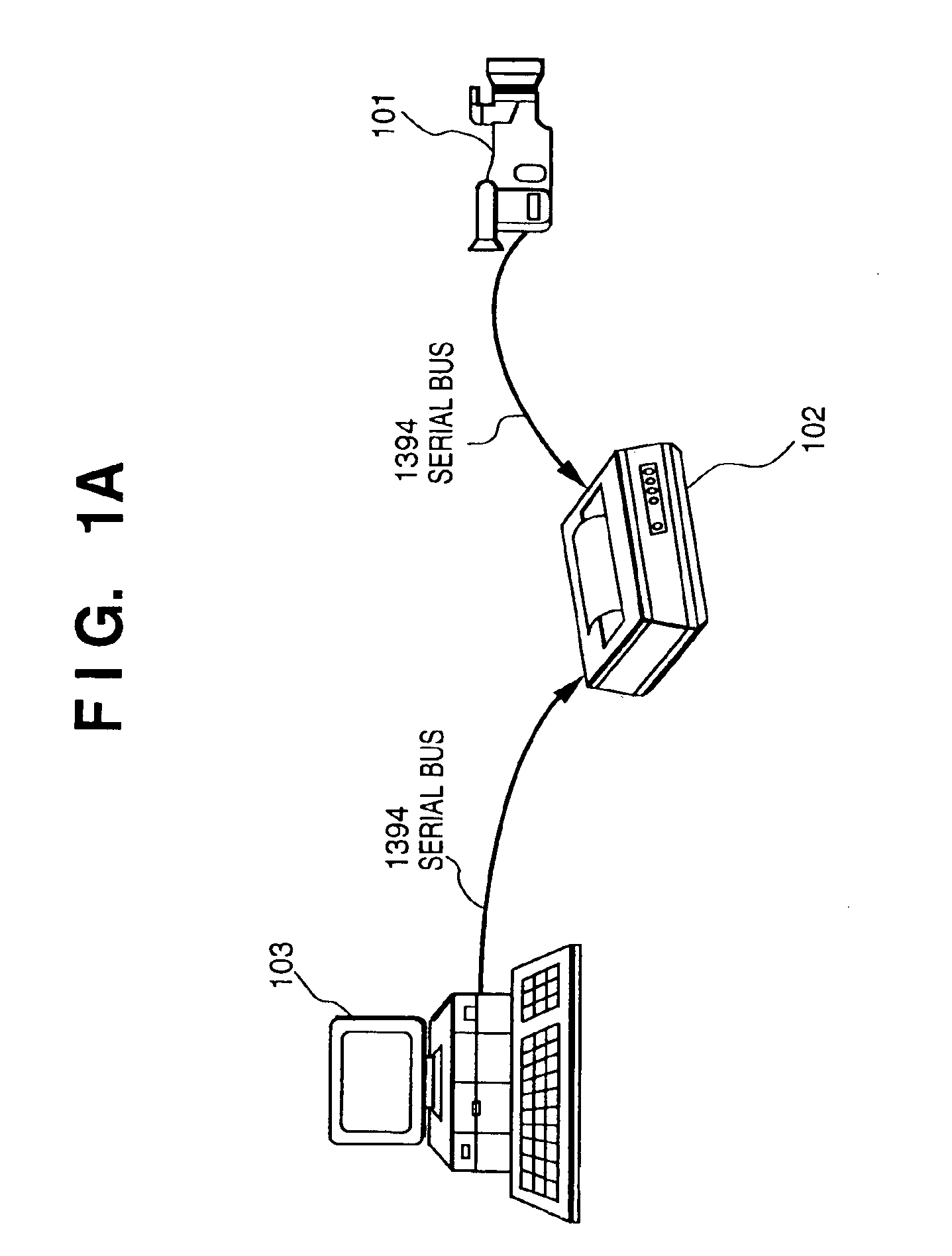
[0126]FIG. 1A shows an example of general construction of a system to which the present invention is applied, where a PC 103, a printer 102 and a digital video camera (DVC) 101 are connected via a 1394 serial bus. Then the outline of the 1394 serial bus will be described below.

[Outline of 1394 Serial Bus]

[0127]With the appearance of general digital video cam recorder (VCR) and digital video disk (DVD) player, there is a need for transferring realtime and large amount data such as video data and audio data (hereinafter referred to as “AV data”). To transfer AV data in realtime to a personal computer (PC) or other digital devices, an interface capable of high-speed data transfer is required. The 1394 serial bus has been developed from the above point.

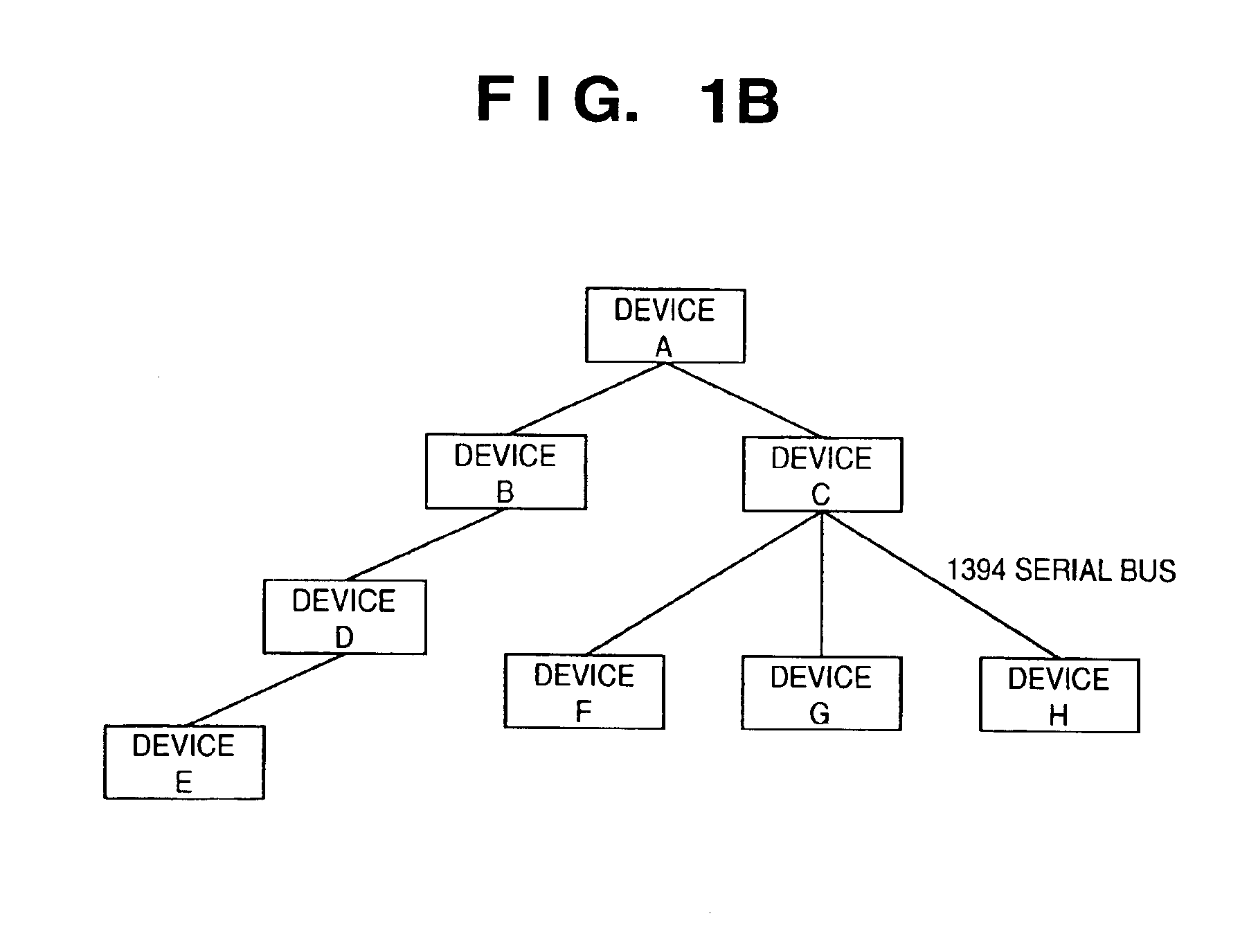
[0128]FIG. 1B shows an example of a network system constructed with a 1394 serial bus. This system comprises devices A to H, and the devices A and B, the devices A and C, the devices B and D, the devices D and E, the dev...

second embodiment

[Second Embodiment]

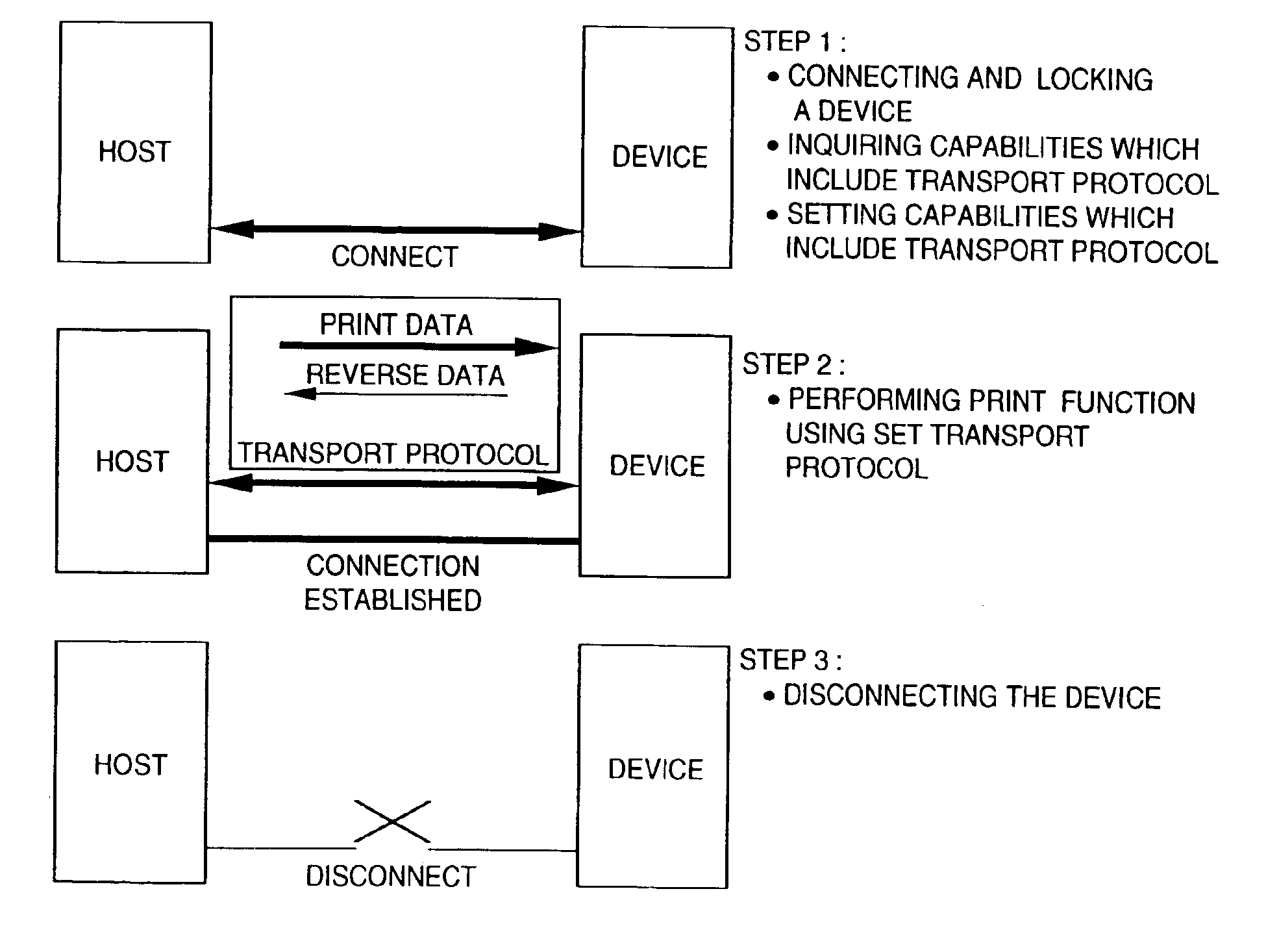
[0400]Next, a second embodiment of the present invention will be described as an example where so-called direct printing is realized in a network constructing by connecting a PC, a printer, other peripheral devices, a recording / reproducing device such as a digital still camera or a digital video camera, with a general-purpose interface such as the 1394 serial bus, so as to solve problems of a digital interface as shown in FIG. 65. In this network, the direct printing is realized by data communication among the devices so as to read video data from the recording / reproducing device into the PC and to directly transfer the video data to the printer.

[0401]That is, the printer can be directly connected to the PC, and it can be directly connected to the digital still camera, or the digital video camera.

[0402]Further, a memory 23, for image mapping, included in a printer 1102 as shown in FIG. 65, has a capacity which changes in accordance with the printing method and typ...

third embodiment

[Third Embodiment]

[0445]Next, a third embodiment of the present invention will be described as an example where the printer 1102 notifies the recording / reproduction device 1101 and the PC 1103 of the performance of a printer engine. The performance of the printer engine is the processing capability of the printer determined by the printhead 24 and the driver 25.

[0446]For example, when using an ink-jet printer, its printing resolution is determined by a nozzle pitch, i.e., an interval between ink-discharge nozzles of the printhead. The higher the printing resolution, the higher the print-output quality, however, the amount of image data increases in proportion to the printing resolution, which dissolves the proportion among data transfer speed, image-data conversion speed, and printing speed of the printer, thus causing wasteful waiting time in image data transfer or print processing.

[0447]FIG. 76 shows the relation between the printing resolution and the amount of image data. If the...


PUM


Abstract

In a system where a digital still camera 1101 is connected to a printer 1102 on a 1394 serial bus, when the digital still camera 1101 as a data transfer originator node transfers image data to the printer 1102 as a data transfer destination node, the printer 1102 sends information on the data processing capability of the printer 1102 to the digital still camera 1101 prior to data transfer. The digital still camera 1101 determines the block size of image data to be transferred in accordance with the data processing capability of the printer 1102, and sends image data of the block size to the printer 1102. The information indicates the capacity of a memory of the printer for storing print data, or the printing capability of a printer engine, i.e., printing resolution, printing speed and the like. Thus, data transfer is always efficiently performed regardless of the data processing capability of the printer 1102.

Description

BACKGROUND OF THE INVENTION[0001]1. Field of the Invention[0002]The present invention relates to a data transmission apparatus, system and method and an image processing apparatus, and more particularly, to a data transmission apparatus, system and method and an image processing apparatus used in a case where an image providing device such as a digital camera is directly connected to an image processing device such as a printer via a serial interface based on, e.g., the IEEE 1394 standards.[0003]Further, the present invention relates to a data transmission apparatus, system and method and an image processing apparatus which interconnect a plurality of electronic devices by using a data communication bus capable of performing data communication by intermixing control signals and data and among the devices.[0004]2. Description of Related Art[0005]Various types of systems which transfer data to a printer via a bus are known. For example, a known technique is to output data from a compu...

Claims


Application Information

Patent Timeline
Patent Type & Authority Patents(United States)
IPC IPC(8): G06F13/00G06F3/12G06F13/42H04L12/40H04L12/64H04L29/06H04N1/00H04N1/333H04N7/24
CPCG06F3/1293H04L12/40058H04L12/40117H04L12/40123H04N1/00278H04N1/00283H04N1/33307H04N1/33376H04N21/4108H04N21/4117H04N21/4135H04N21/4223H04N21/43615H04N21/43632H04N21/44231G06F13/4291H04L69/18H04N2201/0015H04N2201/0034H04N2201/0074H04N2201/0084H04N2201/33328H04N2201/33364H04N2201/33378G06F3/1211G06F3/1232G06F3/1247G06F3/1284
Inventor TATEYAMA, JIROSUZUKI, NAOHISAFUKUNAGA, KOJIKATANO, KIYOSHINAKAMURA, ATSUSHIKOBAYASHI, MAKOTO
Owner CANON KK
Why Eureka
Try Eureka