Method for laser annealing

a laser annealing and metal part technology, applied in the field of annealing, can solve the problems of distortion, side not annealed is subject to stress cracking, and instability or distortion of the outer sheet panel, and achieves the effects of preventing metal part distortion, enhancing material bendability, and reducing stress cracking

Active Publication Date: 2006-06-20
GM GLOBAL TECH OPERATIONS LLC
View PDF7 Cites 3 Cited by
  • Summary
  • Abstract
  • Description
  • Claims
  • Application Information

AI Technical Summary

Benefits of technology

[0009]One advantage of the present invention is that a method for laser annealing a metal part is provided for automotive structures. Another advantage of the present invention is that the method allows laser annealing of aluminum hems in automotive closure components to enhance the bendability of the material during hemming. Yet another advantage of the present invention is that the method uses a laser, which can heat up a small area at a time and cool the trailing spot with additional tooling, thereby preventing distortion of the metal part. Still another advantage of the present invention is that the method allows annealing of aluminum closure sheet panels before a hemming process to alleviate stress cracking. A further advantage of the present invention is that the method has full perimeter annealing capabilities. Yet a further advantage of the present invention is that the method provides decreased cycle time and eliminates operator intervention. Still a further advantage of the present invention is that the method reduces maintenance costs as compared to conventional induction annealing.

Problems solved by technology

An induction current is passed through the coil element to heat up the whole outer perimeter at once, which causes dimensional instability or distortion of the outer sheet panel.
The distortion comes from the heat applied by the induction heating system all at once around the whole outer perimeter of the outer sheet panel.
Further, because only three sides of the outer sheet panel are annealed to eliminate the distortion, the side not annealed is subject to stress cracking.
In addition, if induction heating is used to do portions of the outer sheet panel at a time, separate induction cycles after cooling of the previous sections are not economical due to cycle time.
Further, expensive tape is wrapped around the coil element to prevent the outer sheet panel from touching them, which needs to be changed on a daily basis, increasing maintenance costs and user intervention.

Method used


Image

  • Method for laser annealing
  • Method for laser annealing
  • Method for laser annealing

Examples


Embodiment Construction

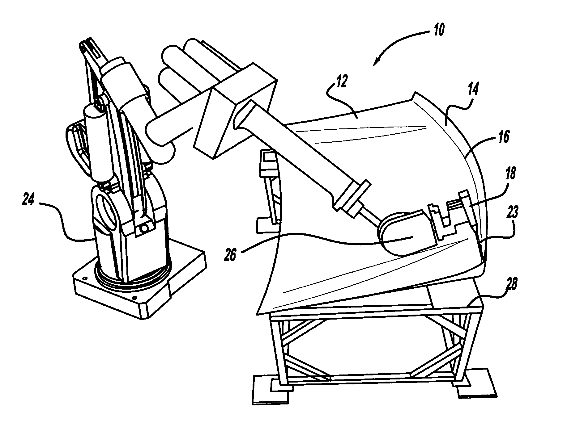
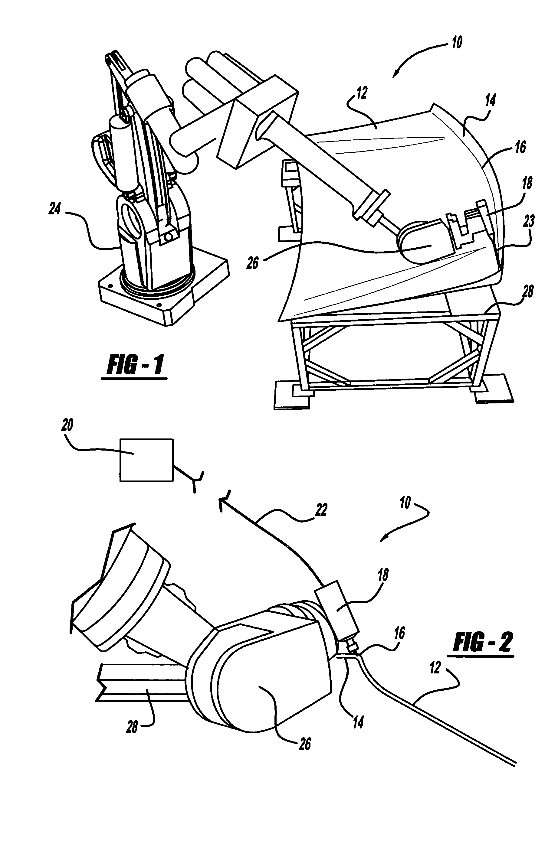
[0014]Referring to the drawings and in particular FIG. 1, one embodiment of a system 10 for carrying out a method, according to the present invention, for laser annealing a metal part such as a sheet panel 12 is illustrated. By way of example, the sheet panel 12 may be an outer sheet panel for a closure panel assembly such as a liftgate of a vehicle (not shown). It should be appreciated that the system 10 anneals the sheet panel 12 prior to hemming in a hemmer (not shown).

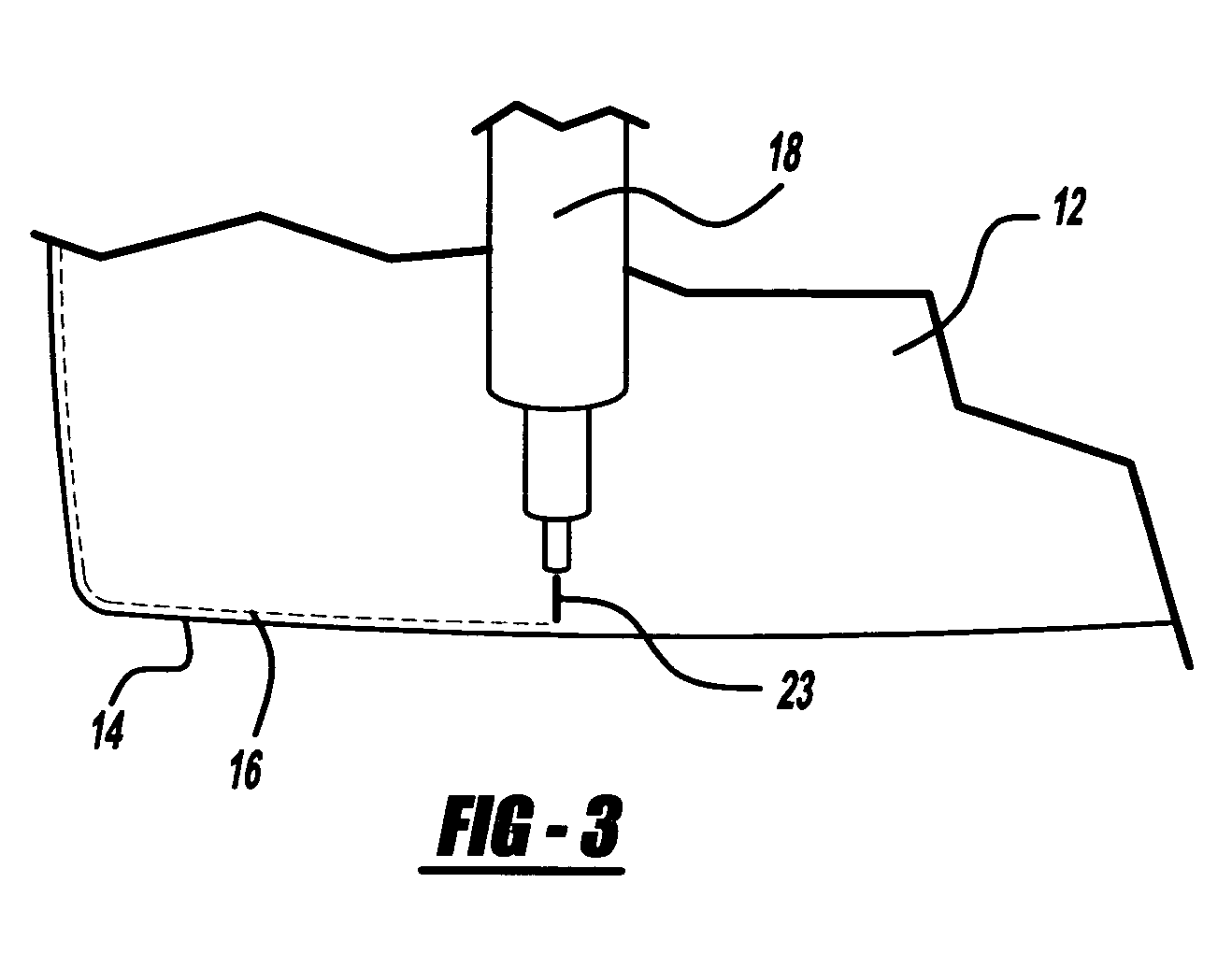
[0015]The sheet panel 12 is generally planar and made of a metal material such as aluminum. The sheet panel 12 has an upstanding flange 14 extending generally perpendicular to a remainder thereof. The upstanding flange 14 has a predetermined height such as approximately ten millimeters (10 mm). The sheet panel 12 also has a radius of curvature or radial bend 16 between the upstanding flange 14 and the remainder of the sheet panel 12. The radial bend 16 has a predetermined length such as approximately five millimete...


PUM

PropertyMeasurementUnit
thicknessaaaaaaaaaa
thicknessaaaaaaaaaa
heightaaaaaaaaaa

Abstract

A method for laser annealing a part includes the steps of providing automated tooling, providing a laser, and providing a metal part to be annealed. The method also includes the steps of moving either one of the laser or metal part by the automated tooling relative to a stationary one of the other laser or metal part. The method further includes the steps of supplying power to the laser to heat a portion of the metal part to a predetermined temperature to anneal the portion of the metal part as the laser and metal part move relative to each other.

Description

TECHNICAL FIELD[0001]The present invention relates generally to annealing and, more particularly, to a method for laser annealing a metal part for assembling automotive structures.BACKGROUND OF THE INVENTION[0002]Metal parts such as aluminum sheet panels are becoming increasingly popular in recent automotive body applications. For examples aluminum sheet panels are used for a closure panel assembly. The closure panel assembly typically includes an outer skin or panel with a generally perpendicular upstanding flange of about ten millimeters (10 mm) in height and an inner section or sheet panel completing the assembly. The closure panel assembly is pressed together in tooling known as a hemmer where the upstanding flange of the outer sheet panel is pressed down onto the inner sheet panel, thereby locking the panels together with a tightness prescribed by a product tolerance.[0003]During vehicle body manufacturing, such aluminum sheet panels, particularly those about one millimeter (1 ...

Claims


Application Information

Patent Timeline
Patent Type & Authority Patents(United States)
IPC IPC(8): C22F1/04
CPCC22F1/04
Inventor NOLAN, STEPHEN R
Owner GM GLOBAL TECH OPERATIONS LLC
Why Eureka
Try Eureka