Control apparatus for brushless DC motor

a control apparatus and dc motor technology, applied in the direction of motor/generator/converter stopper, dynamo-electric converter control, dynamo-electric gear control, etc., can solve the problem of increasing the sine component of the induced voltage proportional to dc motor causes more errors, and the angular velocity of the rotor is often significantly different, so as to improve the estimation accuracy

Active Publication Date: 2006-06-20
HONDA MOTOR CO LTD
View PDF27 Cites 32 Cited by
  • Summary
  • Abstract
  • Description
  • Claims
  • Application Information

AI Technical Summary

Benefits of technology

[0013]The present invention was made in view of the above described circumstances, and has an object to provide a control apparatus for a brushless DC motor capable of improving estimation accuracy when a rotation angle of a rotor is estimated based on an induced voltage in position sensorless control of the brushless DC motor.

Problems solved by technology

However, if there is an error in an inductance component value or the like in the circuit equation on the γδ coordinates that calculates the sine component of the induced voltage, the error in the sine component of the induced voltage increases in proportion to the angular velocity of the rotor.
Thus, for the rotation angle of the rotor estimated based on the PI action with respect to the sine component of the induced voltage, a larger revolution speed of the brushless DC motor causes more errors.
Particularly, when the brushless DC motor is included as a drive source of a vehicle, the angular velocity of the rotor often varies significantly, and frequent loss of synchronization impairs traveling of the vehicle.

Method used


Image

  • Control apparatus for brushless DC motor
  • Control apparatus for brushless DC motor
  • Control apparatus for brushless DC motor

Examples


first embodiment

[0082]Now, a control apparatus for a brushless DC motor according to the invention will be described with reference to the accompanying drawings.

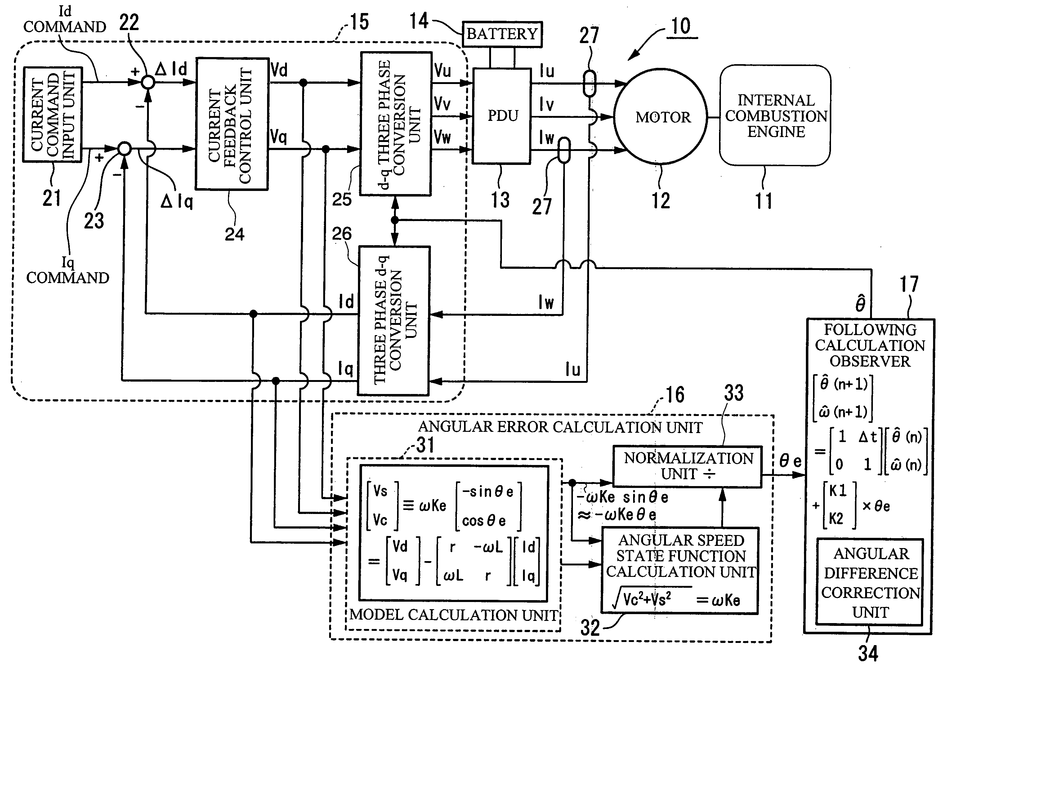
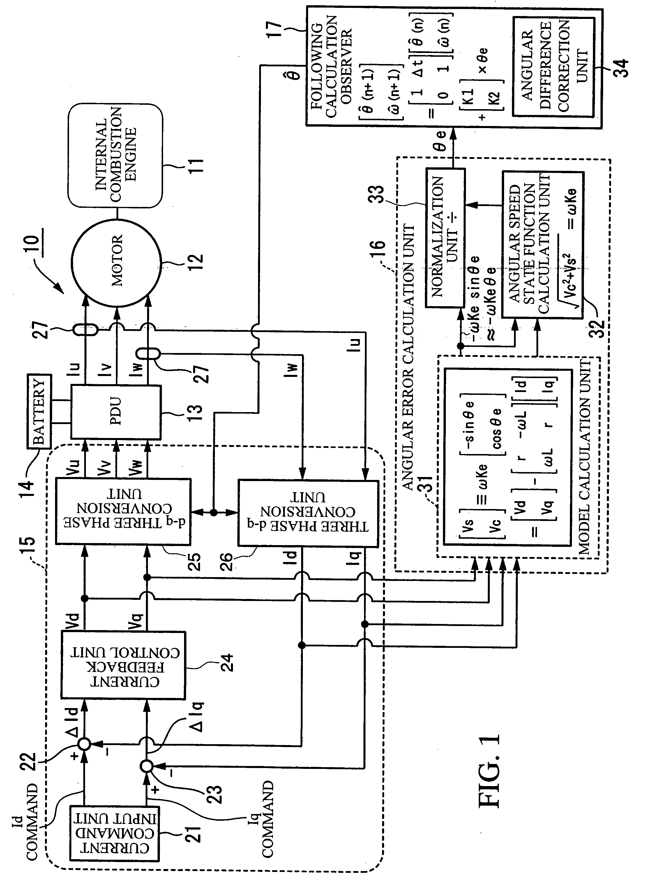
[0083]The control apparatus for a brushless DC motor 10 (hereinafter simply referred to as the motor control apparatus 10) according to the first embodiment drives and controls a brushless DC motor 12 (hereinafter simply referred to as the motor 12) included in, for example, a hybrid vehicle as a drive source together with an internal combustion engine 11. The motor 12 includes a rotor (not shown) connected in series to the internal combustion engine 11 and having a permanent magnet used as a field, and a stator (not shown) that generates a rotating magnetic field for rotating the rotor.

[0084]The motor control apparatus 10 includes, as shown in FIG. 1, a power drive unit (PDU) 13, a battery 14, a control unit 15, an angular error calculation unit 16, and an observer 17.

[0085]In the motor control apparatus 10, a drive and a regenerative oper...

second embodiment

[0141]Now, a control apparatus for a brushless DC motor according to the invention will be described with reference to the accompanying drawings.

[0142]The control apparatus for a brushless DC motor 40 (hereinafter simply referred to as the motor control apparatus 40) according to the second embodiment includes, as shown in FIG. 10, a power drive unit (PDU) 13, a battery 14, a control unit 15, an observer 17, an angular error calculation unit 41, and a control angle correction unit 42.

[0143]The same parts as in the first embodiment are denoted by the same reference numerals, and descriptions thereof will be simplified or omitted.

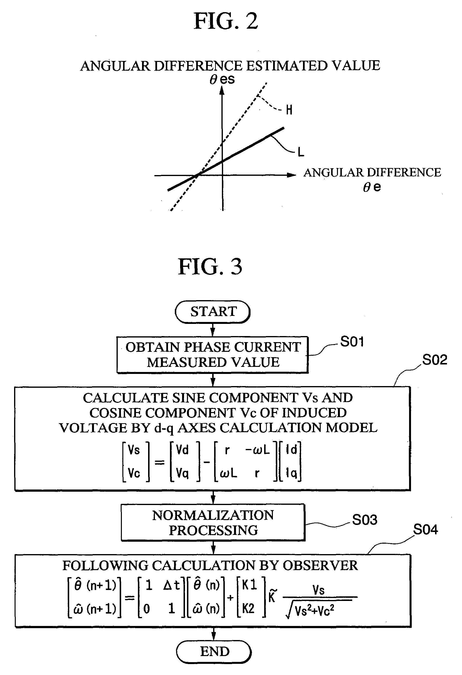
[0144]The angular error calculation unit 41 uses the fact that an angular difference θe can be approximated by a sine value sin θe (θe≈sin θe) when an angular difference θe (=θ−θ^) between an estimated rotation angle θ^ with respect to a rotation angle of a rotor and an actual rotation angle θ is relatively small to calculate the angular difference θe based o...


PUM


Abstract

A control apparatus for a brushless DC motor that rotatably drives the brushless DC motor including a rotor having a permanent magnet, and a stator having stator windings of a plurality of phases that generate a rotating magnetic field for rotating the rotor, by a current passage switching device constituted by a plurality of switching elements and performing successive commutation of current to the stator windings. The control apparatus includes: an angular error calculation device for calculating a sine value and a cosine value of an angular difference between an estimated rotation angle with respect to the rotation angle of the rotor and an actual rotation angle, based on a line voltage that is a difference between phase voltages of the plurality of phases on an input side of the stator winding and phase currents of the plurality of phases; and an observer for calculating the rotation angle of the rotor based on the sine value and the cosine value of the angular difference.

Description

BACKGROUND OF THE INVENTION[0001]1. Field of the Invention[0002]The present invention relates to a control apparatus for a brushless DC motor including a rotor having a permanent magnet, and a stator that generates a rotating magnetic field for rotating the rotor.[0003]Priority is claimed on Japanese Patent Application No. 2003-140726, filed May 19, 2003, the content of which is incorporated herein by reference.[0004]2. Description of the Related Art[0005]Vehicles are known, having a power source for driving a vehicle, including a brushless DC motor using a permanent magnet as a field magnetic, such as fuel cell vehicles, electric vehicles, or hybrid vehicles.[0006]A known control apparatus for such a brushless DC motor is a control apparatus that measures a phase current supplied to each phase of a brushless DC motor, converts a measurement value of the phase current to a d-axis current and a q-axis current on orthogonal coordinates rotating in synchrony with a rotor. For example, ...

Claims


Application Information

Patent Timeline
Patent Type & Authority Patents(United States)
IPC IPC(8): H02P21/12H02P21/00H02P21/13H02P6/18H02P1/18H02P6/06H02P6/08H02P6/182H02P6/28H02P21/06H02P21/14H02P21/22H02P23/12H02P23/14H02P27/04
CPCB60L11/14B60L15/025H02P6/18H02P21/146Y02T10/70H02P2207/05Y02T10/643Y02T10/7077B60L50/16H02P21/18Y02T10/64Y02T10/7072
Inventor IMAI, NOBUYUKITAKAHASHI, YUTAKAMIYAUCHI, MASATO
Owner HONDA MOTOR CO LTD
Why Eureka
Try Eureka