Method and apparatus for providing an additional ground pad and electrical connection for grounding a magnetic recording head

a technology of magnetic recording head and ground pad, which is applied in the field of magnetic hard disk drives, can solve the problems of unreliable electrical resistance of conductive glue, difficult control, and difficulty in controlling the flatness of the slider after mounting into the hga, and adds to the cost and duration of the manufacturing process

Inactive Publication Date: 2006-06-20
SAE MAGNETICS (HK) LTD
View PDF4 Cites 63 Cited by
  • Summary
  • Abstract
  • Description
  • Claims
  • Application Information

AI Technical Summary

Problems solved by technology

Most of all, the electrical resistance of the conductive glue is unreliable and hard to control.
In addition, it is difficult to control the flatness of the slider after mounted into the HGA, which is another critical parameter.
In addition, to apply and cure the conductive glue in the HGA assembly requires many processes adding to the cost and duration of the manufacturing

Method used


Image

  • Method and apparatus for providing an additional ground pad and electrical connection for grounding a magnetic recording head
  • Method and apparatus for providing an additional ground pad and electrical connection for grounding a magnetic recording head
  • Method and apparatus for providing an additional ground pad and electrical connection for grounding a magnetic recording head

Examples


first embodiment

[0022]Referring to FIG. 3, the present invention is shown. In this embodiment, a slider 201 is provided including read and write electrical components at a trailing end of the slider. Bonding pads 209 and 211 are provided on the slider for electrically connecting the read and write electrical components to electrical components on the suspension 221. In this embodiment, the electrical components of the suspension include four conductive traces 205, 207 that are coupled to bonding pads 215, 217, respectively, for read / write signals. In a typical suspension as known in the art, the conductive traces 205, 207 may be incorporated into the suspension 221, or created separately in a flex circuit or the like that is coupled to the suspension. Also, the traces are electrically coupled to electrical components of the disk drive (e.g., a preamplifier, not shown specifically in FIG. 3) that control the reading of data from and writing of data to the storage medium.

[0023]According to this embod...

second embodiment

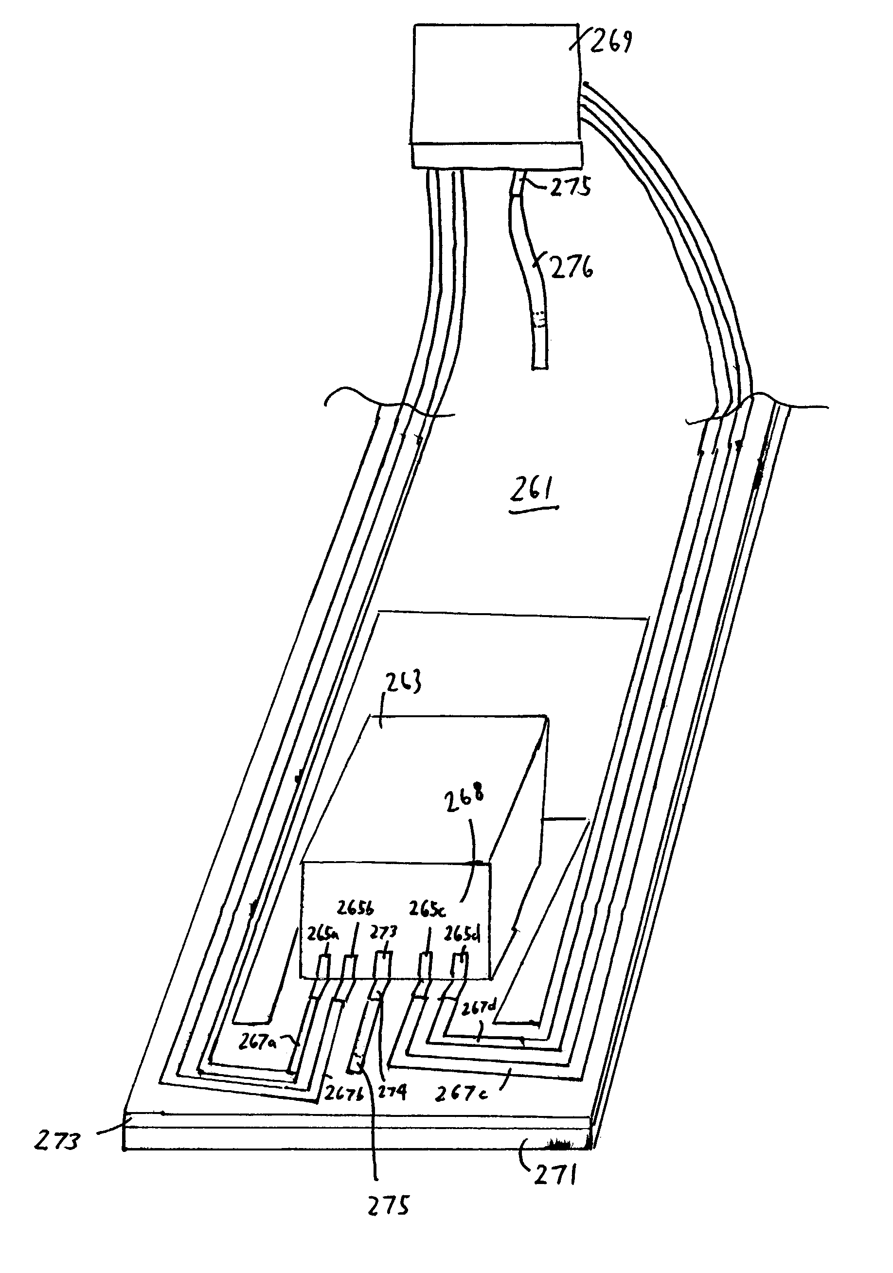
[0032]Referring to FIG. 8, a second embodiment for electrically coupling a trace segment to the stainless steel base is shown. In this embodiment, the traces are created through an additive process such as in a circuit integrated suspension (CIS). In such an additive process, the dielectric layer 291 is deposited onto a stainless steel base 292 and then the conductive trace 293 is deposited on top of the dielectric layer 291. In this embodiment, an opening 290 is made in the dielectric layer 291. For example, after the dielectric layer 291 is deposited onto the stainless steel base 292, the opening 290 may be formed into the dielectric layer through an etching process. Alternatively, the dielectric layer 291 may be deposited in such a manner so as to create an opening to the base 292 during the deposition process. After the opening is created, the conductive trace 293 is deposited into the opening so as to create an electrical connection (e.g., between one of the trace segments 275,...

third embodiment

[0033]Referring to FIG. 9, a third embodiment for electrically coupling a trace segment to the stainless steel base is shown. In this embodiment, the copper traces are formed as part of a flex suspension assembly (FSA). Referring to FIG. 9, the FSA includes a copper ground plane 301, a dielectric layer 303, and metal traces including trace segment 305. Once formed, the FSA is then attached to the suspension 315, which can be made entirely of stainless steel. The slider 307 can then be attached to the flexure of the suspension and electrically coupled to the copper trace segment via a separate ground pad 308 on the surface of the slider 307. In this embodiment, an opening 310 is made in the dielectric layer 303 so that trace segment 305 can make electrical contact with the copper ground plane 301. As with the embodiment shown in FIG. 7, the electrical connection may be made by providing a separate, conductive material (e.g., a gold ball or solder ball) in the opening coupling the tra...


PUM


Abstract

Method and apparatus are presented for electrically coupling a slider to ground. In one embodiment, a bonding pad is provided on a side of the slider body separate from the bonding pad(s) used for read/write signals. This separate bonding pad is electrically coupled within the slider body to components that are to be coupled to ground. A separate conductor provided on the suspension (e.g., a trace, a flex circuit, etc.) may be electrically coupled to the separate bonding pad via gold ball bonding. The conductor is also coupled to ground in the hard-disk drive device (e.g., via the preamplifier). The use of the separated bonding pad and trace may negate the need to use a conductive adhesive to electrically ground the slider via its attachment to the tongue of a slider.

Description

[0001]The present application claims priority to U.S. application No. 60 / 417,665 filed Oct. 11, 2002.BACKGROUND INFORMATION[0002]The present invention relates to magnetic hard disk drives. More specifically, the present invention relates to a method and apparatus for grounding a magnetic recording head that may avoid the use of a conductive adhesive.[0003]A disk drive for data recording uses magnetic recording heads for writing and reading data on recording disks. The recording heads are built on a substrate, called a wafer, which is made of electrically conductive material, such as AlTiC, with processes similar to those for semiconductor devices. Gold pads on the external surface of the recording head are electrically connected to the recording devices through internal electrical paths built during the wafer-level processes. The wafer is then sliced into rectangular pieces with an individual recording head on each piece with the substrate attached, which is called a slider. Afterwa...

Claims


Application Information

Patent Timeline
IPC IPC(8): G11B5/55G11B5/60B24B37/00B24D18/00G11B5/48
CPCB24B37/00B24D18/00H05K3/3442G11B5/4853H05K2201/10727H05K1/0215Y02P70/50
Inventor FU, YENCHA, ELLISWANG, PO-KANGTIAN, HONGHERNANDEZ, MANUELTANG, YAW-SHINGHU, BEN
Owner SAE MAGNETICS (HK) LTD
Why Eureka
Try Eureka