System, method, and apparatus for visual authentication

a technology of visual authentication and system, applied in the field of authentication, can solve the problems of inability to guarantee the reliability of the authentication of the user's password transmitted over an unsecured network, the inability to protect the user's identity from unauthorized duplication, and the inability to reliably verify the authenticity of the user's password, etc., and achieve the effect of reliable authentication and positive authentication

Inactive Publication Date: 2006-06-20
TEICHER MORDECHAI
View PDF14 Cites 71 Cited by
  • Summary
  • Abstract
  • Description
  • Claims
  • Application Information

AI Technical Summary

Benefits of technology

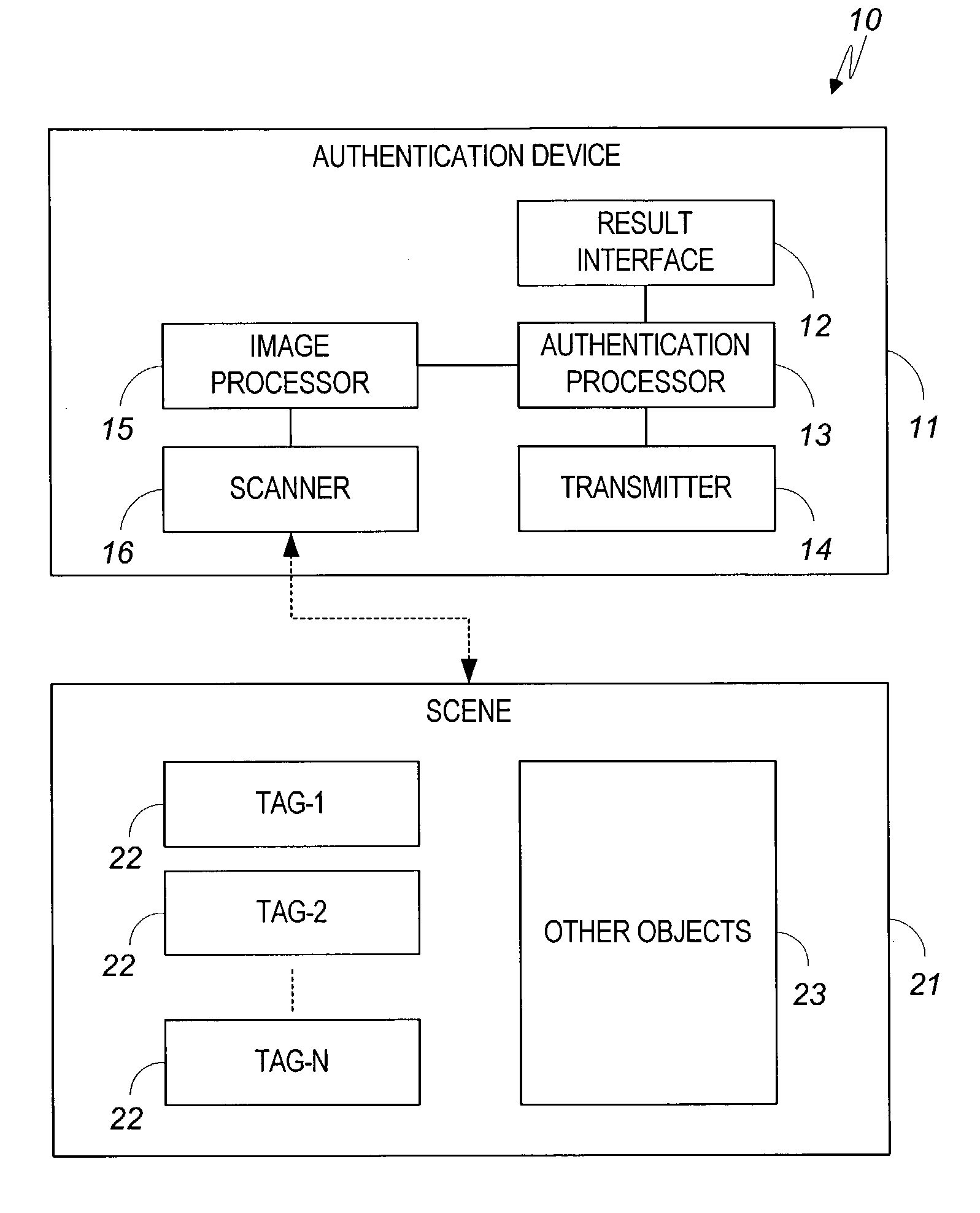
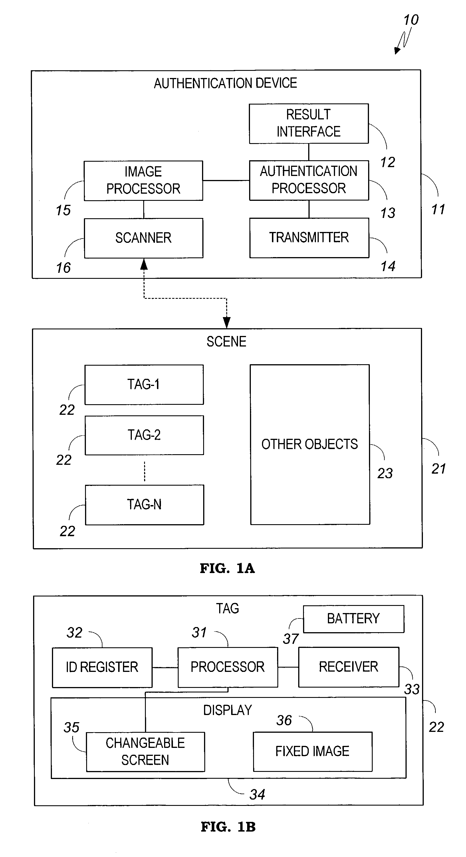
[0008]By “tag” is meant a small standalone device that is easy to carry or wear by humans or to attach to objects, and which includes a display showing machine-readable symbols. The display may use any technology to represent the symbols, such as printing, front-lit or back-lit liquid crystal (LCD), light emitting diodes (LED), light bulbs, or electrically-controlled mechanical shutters.
[0013]Another object of the present invention is to reduce the amount of visual space used for authentication.
[0017]Briefly, the present invention adds a processor-controlled changeable screen to a tag, in order to display a response string that authenticates the content of the tag. The response string is generated with respect to either a challenge string received by the tag, or to a time stamp retrieved from a real-time clock included in the tag. An authentication device scans the tag, reads it contents, calculates the expected response string, and compares the readout response with the expected response to decide authenticity. Repeated readouts can accumulate to provide reliable authentication even if the size of the changeable screen is small and allows displaying only a minimal amount of data. Part of the changeable screen can be used to display a changeable message, while the response displayed on the other part of the screen will then authenticate the message as well. The authentication device can output an image of a scene, and spot authenticated and unauthenticated objects and tags within the image.
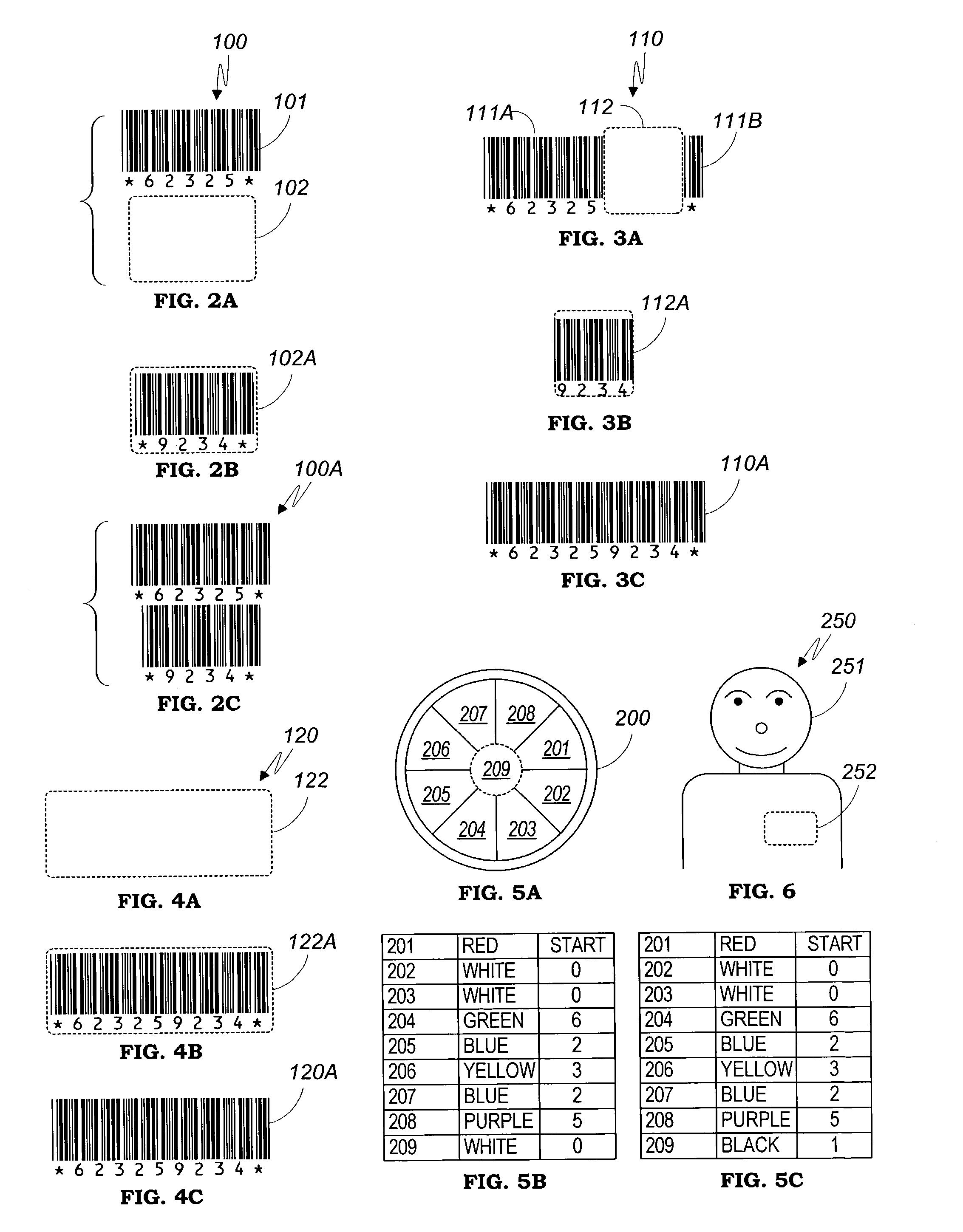
[0022]Additionally, in accordance to another embodiment of the present invention, a changeable screen with limited space can still provide a response string of a desirable length via a series of snapshots, and the image processor of the authentication device will then compose the readout string from the series of snapshots. Alternatively, a changeable screen with limited space can still provide reliable authentication by repeating a series of challenge-and-response sessions, and concluding a positive authentication result only upon reaching a predetermined number of successful matches between consecutive readout response strings and their corresponding expected response strings.

Problems solved by technology

Thus, for example, a password transmitted over an unsecured network is not considered reliable for authentication, because it can be intercepted and replayed by an attacker.
However, this very advantage makes such codes also vulnerable to unauthorized duplication.
However, none of the methods of the prior art offers robust protection against a sophisticated attacker who uses affordable, off-the-shelf equipment to read and reproduce the symbols.

Method used


Image

  • System, method, and apparatus for visual authentication
  • System, method, and apparatus for visual authentication
  • System, method, and apparatus for visual authentication

Examples


embodiment 80

[0075]FIG. 14A illustrates an embodiment 80 of tearing sensor 40 of FIG. 12. Housing 82 forms part of tag 22C and cannot be separated therefrom without destroying tag 22C. Housing 82 contains two contact points 85A and 85B, which are electrically-connected by magnetic conductor 83. Wires 81A and 81B connect contact points 81A and 81B to eraser 41, which continually monitors the electrical resistance between these wires. The car's metal body 89 attracts magnetic conductor 83 and overcomes spring 84 which tries to pull magnetic conductor 83 away from contact points 85A–B. However, when tag 22C, along with housing 82, is removed from car body 89 even momentarily, spring 84 pulls magnetic conductor 83 away from contact points 85A–B, which changes the electrical resistance between wires 81A–B as measured by eraser 41. This triggers eraser 41 to erase the contents of ID register 32.

embodiment 90

[0076]FIG. 14B illustrates an alternative embodiment 90 for tearing sensor 40 of FIG. 12. In this case, wires 91A–91B are connected by a conducting plate 93, which is attached by a strong adhesive to object 99. The resistance between wires 91A–B is monitored by eraser 41. When tag 22C is removed from object 99, conducting plate 93 will be broken, which triggers eraser 41 to erase the contents of ID register 32.

[0077]Tearing sensors can be applied also when the tag of the present invention is to be attached to a human. For example, a bracelet that must be broken for removal from one's wrist may include conductive materials to serve as a tearing sensor. Then, if a tag connected to the bracelet is used to identify special access rights or privileges granted personally to the wearer (e.g., in connection to a specific event or for specific services), such rights will not transferable to others because the tag will become inoperable upon removal from the wrist of its original wearer.

[0078...


PUM


Abstract

A visual tag having an imprinted image, a processor for calculating a response string corresponding to the content of the imprinted image and a challenge string, and a changeable screen to display the response string in machine-readable symbols. An authentication device reads the displayed symbols, and authenticates the displayed contents corresponding to the challenge string. The challenge string is generated either according to a random generator within the authentication device, or according to a real-time clock. A plurality of tags or objects can be authenticated and spotted within an image. The tag can also authenticate inputted messages and credentials.

Description

CROSS-REFERENCE TO RELATED APPLICATIONS[0001]Applicant hereby claims priority of U.S. Provisional Patent Application U.S. Ser. No. 60 / 442083, filing date Jan. 20, 2003, entitled “SYSTEM METHOD AND APPARATUS FOR VISUAL AUTHENTICATION”.BACKGROUND OF THE INVENTION[0002]The present invention relates to authentication, and, in particular, to the authentication of visual symbols.[0003]Authentication is the verification of the identity of a person, object, or process. In a communication system, authentication verifies that messages come from their stated source. In an access control system, physical access may require authentication by photo ID, password, or biometric data. Paper document authentication is often made by checking a handwritten signature. Credit card transactions involve PIN or signature to authenticate the cardholder.[0004]With growing threats from both crime and terrorism, authentication becomes more and more important, and the authentication methods need to be more and mo...

Claims


Application Information

Patent Timeline
Patent Type & Authority Patents(United States)
IPC IPC(8): H04L9/00G07C9/00
CPCG07C9/00015G06K7/1095G07C9/21
Inventor TEICHER, MORDECHAI
Owner TEICHER MORDECHAI
Why Eureka
Try Eureka