Expanded downhole screen systems and method

a tubular screen and screen system technology, applied in the direction of drilling pipes, directional drilling, drilling/well accessories, etc., can solve the problems of limiting the length of screen installation, spiraling increases drag, and difficult cleaning of boreholes, so as to reduce spiraling of boreholes, improve the quality of boreholes, and facilitate tubular insertion

Active Publication Date: 2006-06-27
HALLIBURTON ENERGY SERVICES INC
View PDF15 Cites 10 Cited by
  • Summary
  • Abstract
  • Description
  • Claims
  • Application Information

AI Technical Summary

Benefits of technology

[0006]An improved system and method are disclosed for expanding fluid-permeable tubular members or “screens” in an open-hole wellbore to recover hydrocarbons from subterranean formations. According to one aspect of this invention, deviated borehole sections may be drilled with improved borehole quality, characterized in part by reduced borehole spiraling. This allows for easier insertion of the tubular. The tubular may then be expanded within the borehole.
[0007]There are significant advantages associated with this method. The invention leads to a lower expansion ratio of the tubular, which minimizes any reduction in mechanical properties of the screen, such as collapse strength. A larger tubular may be used to reduce the amount of expansion required, achieving expansion ratios of less than approximately 15%, and preferably less than 10%. Such reduced expansion requires less axial force to expand the screen and results in better post-expansion collapse strength. Typically, the screen is expanded to a point where its outer wall places a stress on the interior wall of the wellbore, thereby providing support to the walls of the wellbore. Once expanded, the space between the screen and the wellbore may largely be eliminated, along with the need for a large gravel pack otherwise required to fill the annular space with particulate to support the formation and maintain permeability. Because less pressure is used in the installation of the fluid-permeable tubular, it is more reliable, efficient, and durable.
[0008]The present method is further preferable to existing technologies because it results in a higher production yield, has lower drawdown, allows for a larger internal diameter for intervention work, and simplifies installation.

Problems solved by technology

One major problem associated with existing screen expansion techniques is commonly referred to as “spiraling.” Poor hole quality associated with spiraling makes borehole cleaning and screen installation more difficult.
Spiraling increases the drag and limits the length of screen that can be installed.
Any annulus between the screen and wellbore will significantly reduce the benefits associated with an expandable screen completion.

Method used


Image

  • Expanded downhole screen systems and method
  • Expanded downhole screen systems and method
  • Expanded downhole screen systems and method

Examples


Embodiment Construction

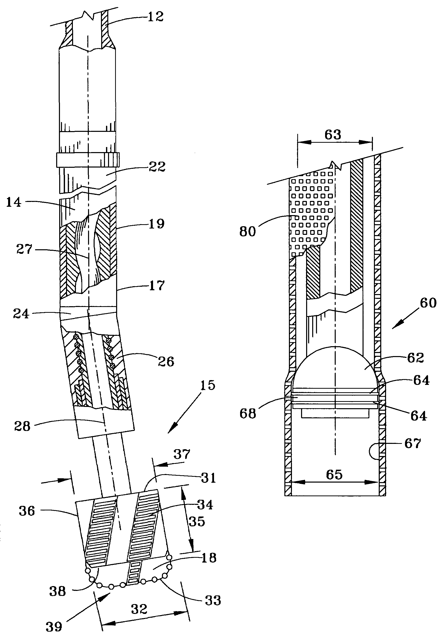
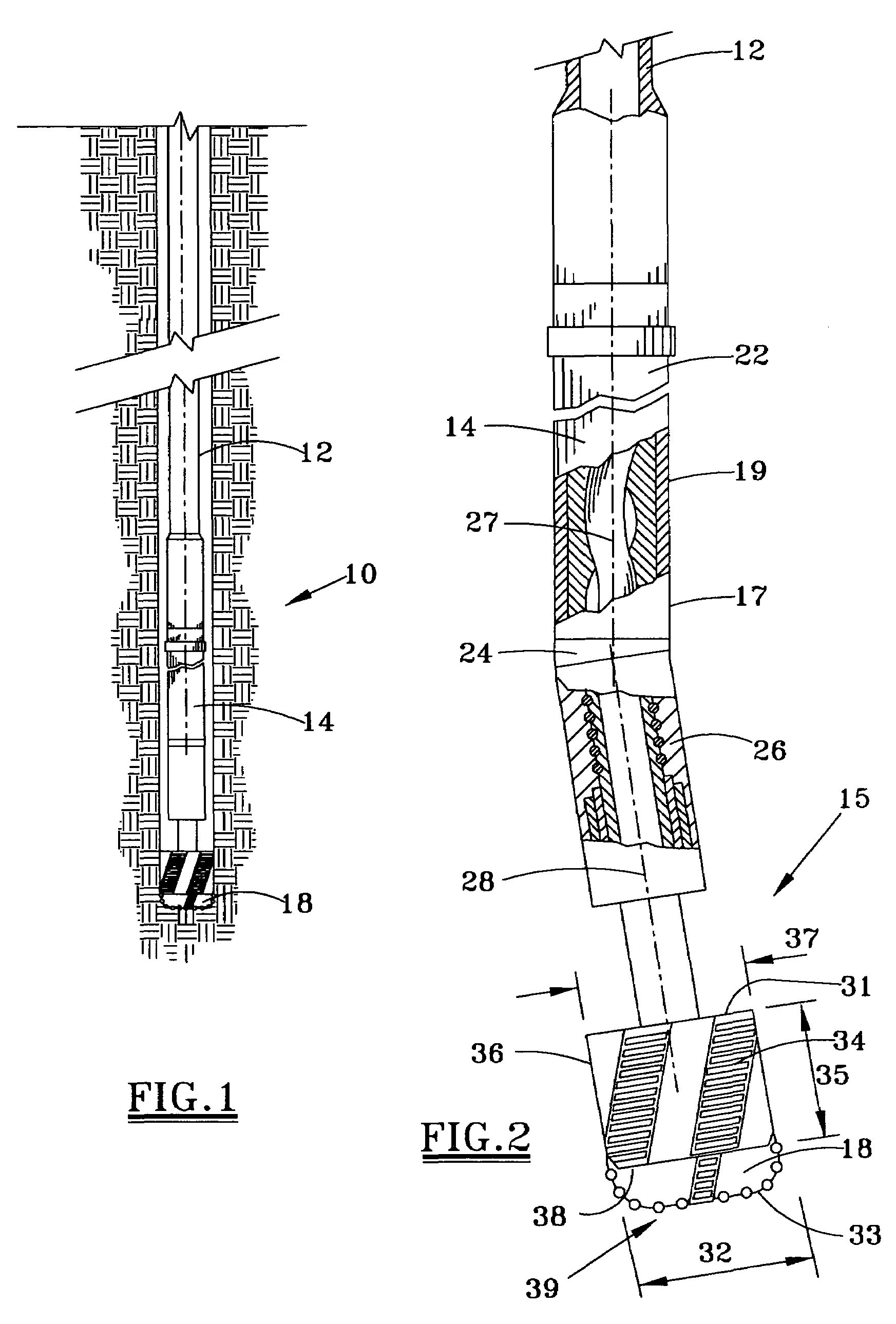
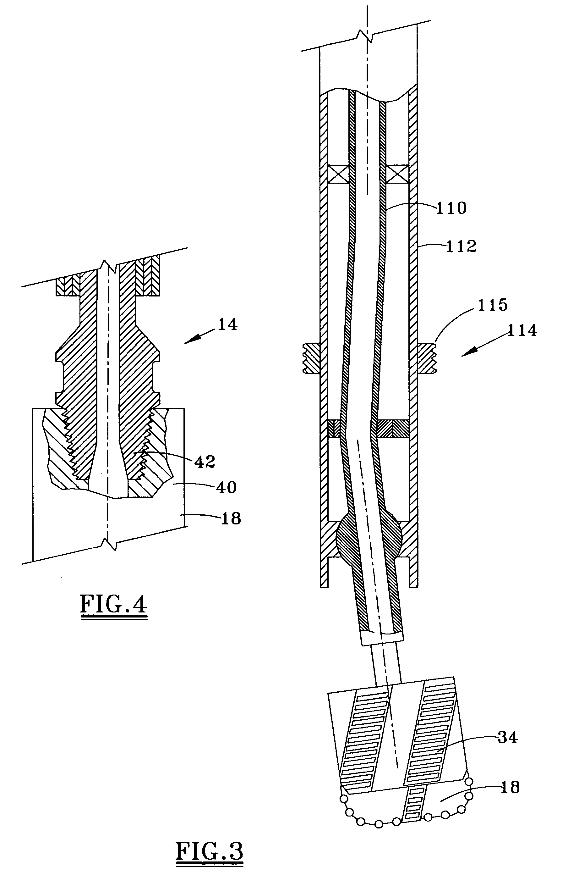
[0020]FIG. 1 generally illustrates drilling a straight section of a well, with a bottom hole assembly (BHA) 10 positioned at the lower end of a drill string 12. The BHA 10 includes a fluid powered downhole motor 14 for rotating a bit 18 during drilling. FIG. 2, by contrast, illustrates a BHA configured for drilling a deviated portion of a well. The motor 14 for drilling deviated portions of the well may be a “positive displacement motor” (PDM) having a lobed rotor. In most cases, the PDM is a “bent housing motor” (BHM), typically having a bend 24 of less than 3 degrees. The bend 24 of a PDM is between the upper power section having rotational axis 27 and a lower bearing section having rotational axis 28 in the motor housing, so that the axis 28 for the bit 18 is offset at the selected bend 24 from the axis 27. The lower bearing section 26 includes a bearing package assembly which conventionally comprises both thrust and radial bearings. The PDM 14 may be run “slick”, meaning that th...


PUM


Abstract

An improved system and method is disclosed for expanding a fluid permeable tubular downhole in an open hole completion. A high quality borehole is first drilled using a bottomhole assembly having a long gauge bit and a short bit-to-bend ratio. A fluid-permeable tubular is then inserted into an open-hole portion of the wellbore and preferably expanded in place. The expandable tubular may include an external filtering medium. Hydrocarbons may pass from the formation through the expanded fluid permeable tubular and into the borehole, to be recovered.

Description

FIELD OF THE INVENTION[0001]The invention relates to a system and method to expand tubular screens in an open-hole wellbore to recover hydrocarbons from subterranean formations.BACKGROUND OF THE INVENTION[0002]Oil and gas wells are drilled with a wellbore into which tubular segments, such as steel casing, may be inserted and installed. Fluid-permeable tubular members or “screens” are frequently used in the production zone of an open-hole wellbore to recover hydrocarbons from subterranean formations. Screens permit fluid to pass from such fluid-bearing formations into a tubular string for recovery.[0003]Screens may be expanded in the wellbore in much the same way that conventional tubulars such as casing may be expanded. Expandable sand screen (“ESS”) generally consists of a perforated or slotted base pipe, and may include woven filtering material and a protective, perforated outer shroud. Both the base pipe and the outer shroud are expandable. The woven filter is typically arranged ...

Claims


Application Information

Patent Timeline
Patent Type & Authority Patents(United States)
IPC IPC(8): E21B23/02E21B43/08E21B43/10
CPCE21B7/067E21B43/108E21B43/103E21B43/08
Inventor CHEN, CHENKANG DAVIDGLEITMAN, DANIEL DAVIDRAO, M. VIKRAM
Owner HALLIBURTON ENERGY SERVICES INC
Why Eureka
Try Eureka