Methods of preparing electrochemical cells
a technology applied in the field of electrochemical cells and separators, can solve problems such as short circuit of cells
- Summary
- Abstract
- Description
- Claims
- Application Information
AI Technical Summary
Benefits of technology
Problems solved by technology
Method used
Image
Examples
example 1
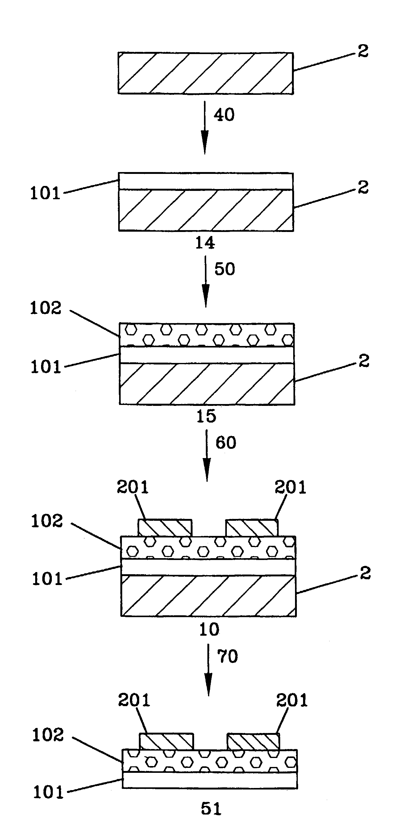
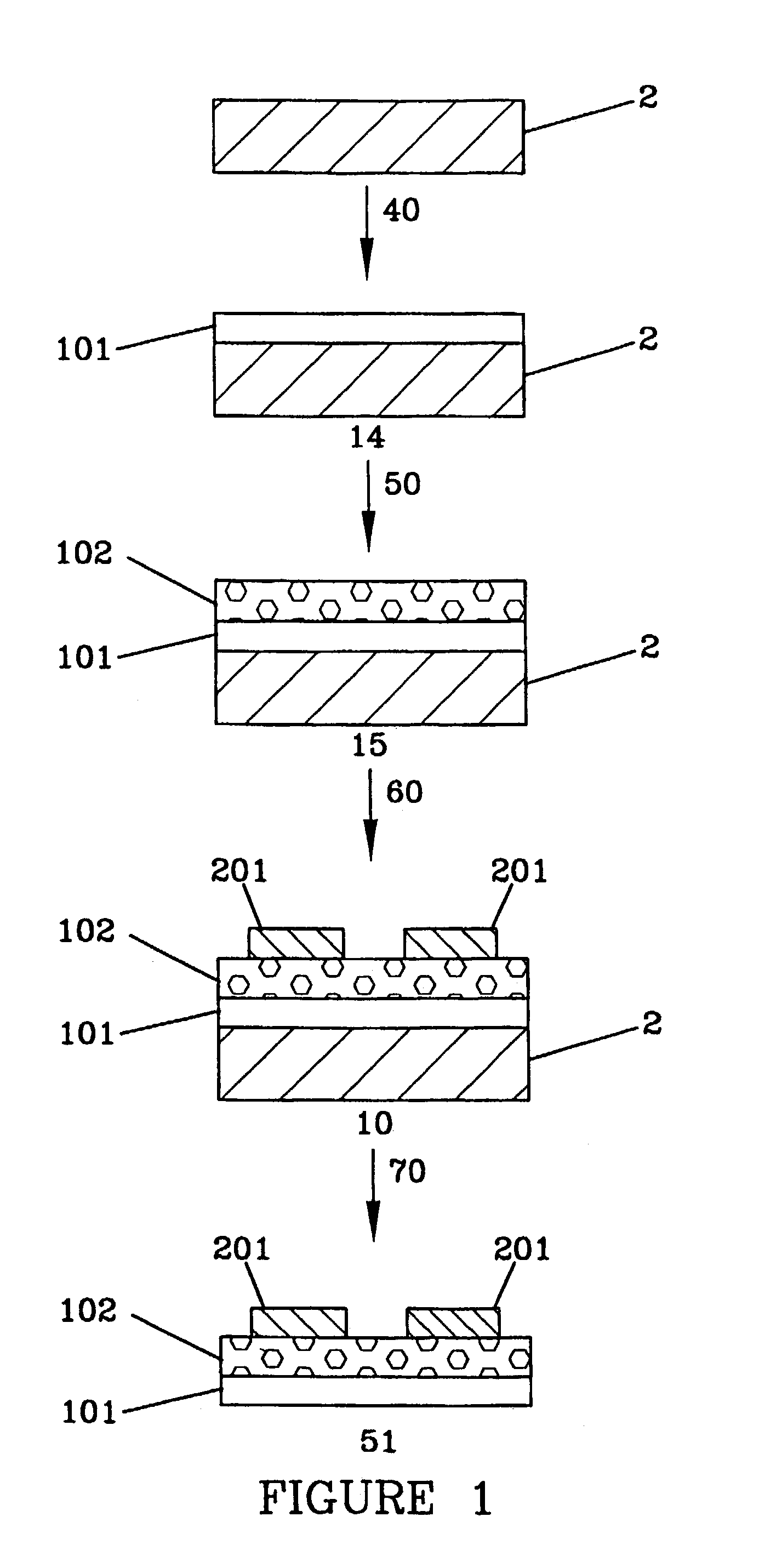
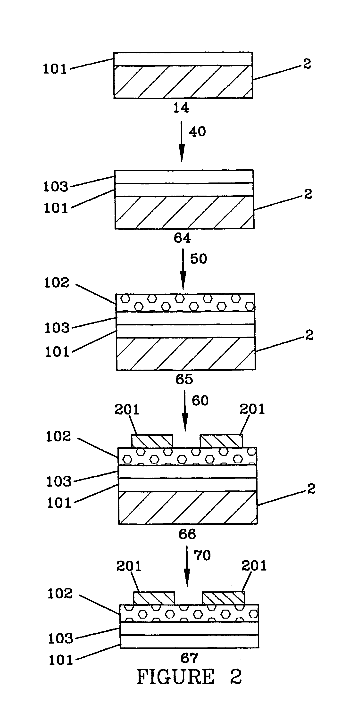
[0182]A coating mixture for a first step of making a protective coating layer was prepared by adding 17.5 g of a 4% by weight solution of polyvinyl alcohol (AIRVOL 125, a trademark for polyvinyl alcohol polymers available from Air Products, Inc., Allentown, Pa.) in water to 10.0 g of a 7.0% by weight solids solution of boehmite sol in water (CATALOID AS-3, a trademark for aluminum boehmite sols available from Catalysts & Chemicals Ind. Co., Ltd., Tokyo, Japan) and stirring to mix the materials. 0.10 g of ZONYL FSO-100, a trademark for non-ionic fluorochemical compounds available from E.I. duPont de Nemours, Wilmington, Del., was added with stirring to make the sol gel coating mixture. Using a gap coating with a slot opening of a set thickness to doctor the coating, the sol gel coating mixture was applied to the non-treated surface of 23 micron thick MELINEX 6328, a trademark for polyethylene terephthalate (PET) films available from DuPont Teijin Films, Wilmington, Del. After air dry...
example 2
[0188]A free-standing cathode / separator assembly was prepared as described in Example 1, except that a 5% solution of styrene-4-sulfonic acid sodium salt (available from Aldrich Chemical Company, Milwaukee, Wis.) was substituted for the multifunctional monomer coating mixture with the latent lithium ion catalyst. This free-standing cathode / separator assembly of Example 2 gave similar results when fabricated into rechargeable electrochemical cells as those found with the cathode / separator assembly of Example 1.
example 3
[0189]A free-standing cathode / separator assembly was prepared as described in Example 1, except that a 7.0% by weight solids solution of ammonium zirconyl carbonate prepared by adding water to BACOTE 20, a trademark for zirconium compounds available from Magnesium Eleckton, Flemington, N.J., was substituted for the CATALOID AS-3 in both the first step of making the protective coating layer and in the step of making the microporous xerogel separator layer. The ammonium zirconyl carbonate is a precursor to zirconium oxide sols and, upon coating and drying, provides a zirconium oxide xerogel layer. This free-standing cathode / separator assembly of Example 3 showed more than twice the mechancial strength and flexibility without cracking as found with the free-standing cathode / separator assembly of Example 1. The free-standing cathode / separator assembly of Example 3 gave similar results when fabricated into rechargeable electrochemical cells as those found with the cathode / separator assem...
PUM
| Property | Measurement | Unit |
|---|---|---|
| thicknesses | aaaaa | aaaaa |
| thickness | aaaaa | aaaaa |
| thickness | aaaaa | aaaaa |
Abstract
Description
Claims
Application Information
 - R&D
- Intellectual Property
- Life Sciences
- Materials
- Tech Scout
- Unparalleled Data Quality
- Higher Quality Content
- 60% Fewer Hallucinations
Browse by: Latest US Patents, China's latest patents, Technical Efficacy Thesaurus, Application Domain, Technology Topic, Popular Technical Reports.
© 2025 PatSnap. All rights reserved.Legal|Privacy policy|Modern Slavery Act Transparency Statement|Sitemap|About US| Contact US: help@patsnap.com


